Control system and control method of refrigerator

A technology for controlling systems and refrigerators, applied in household refrigeration devices, defrosting, lighting and heating equipment, etc., can solve problems such as poor dehumidification effect, and achieve optimal dehumidification effect

Inactive Publication Date: 2017-11-03
HAIER SMART HOME CO LTD
View PDF3 Cites 4 Cited by
  • Summary
  • Abstract
  • Description
  • Claims
  • Application Information

AI Technical Summary

Problems solved by technology

In this technology, the dehumidification effect is very poor

Method used


Image

  • Control system and control method of refrigerator
  • Control system and control method of refrigerator
  • Control system and control method of refrigerator

Examples


no. 1 approach

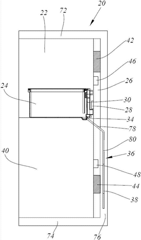
[0053] Such as figure 1 Shown, the first embodiment of the present invention, this embodiment discloses a kind of refrigerator, comprises the box body 20 that constitutes refrigerating room 22, is used to open and close the door of refrigerating room 22 of refrigerating room 22, and is located in refrigerating room The drawer 24 in the 22, the evaporator, the air duct 26, the air outlet 28 located between the air duct 26 and the refrigerator compartment 22 and the damper (not shown) that can selectively open or close the air outlet 28.

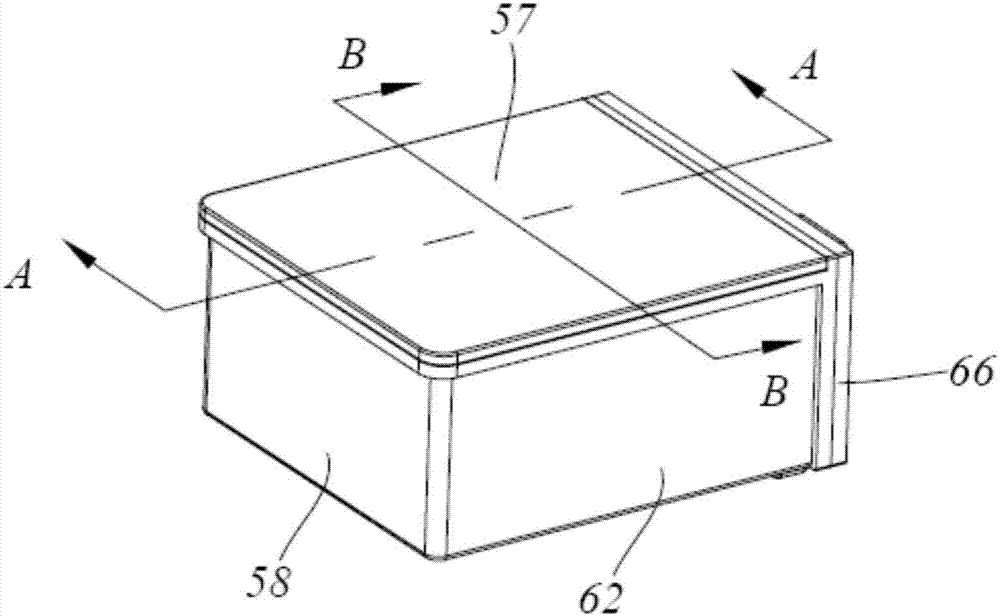
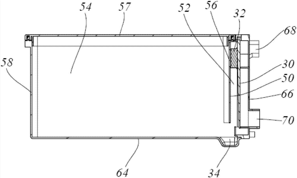
[0054] further reference figure 1 and image 3 , wherein, the drawer 24 is provided with a condensation metal plate 30, and the drawer 24 is provided with a dehumidification fan 32 that allows the air in the drawer 24 to flow to the condensation metal plate 30, and one side of the condensation metal plate 30 is exposed inside the drawer 24. The other side of the condensation metal plate 30 can receive the cold air blown from the air outlet 2...


PUM


Abstract

The invention discloses a control system and control method of a refrigerator. A condensation metal plate is arranged in a drawer of the refrigerator, a dehumidifying fan used for enabling air in the drawer to flow to the condensation metal plate is arranged in the drawer, and a groove used for collecting condensation is formed in the drawer; the refrigerator further comprises a drain pipe and a water pan, the drain pipe comprises a U-shaped pipe part and a heating wire, and the two ends of the drain pipe communicate with the groove and the water pan correspondingly; the control system comprises a main control panel and a humidity sensor arranged in the drawer and used for monitoring the humidity in the drawer, and the main control panel is electrically connected with the humidity sensor to obtain the humidity value monitored by the humidity sensor and then conduct treatment; and the main control panel controls opening or closing of an air door and the dehumidifying fan, and the main control panel is electrically connected with the heating wire to control heating or stopping of heating of the heating wire. According to the control system and control method of the refrigerator, the dehumidifying effect of the drawer in a refrigerating chamber is more excellent.

Description

technical field [0001] The invention relates to the technical field of household appliances, in particular to a control system and a control method for a refrigerator. Background technique [0002] Usually, the refrigerator includes a temperature-changing room, and a circulating air duct is arranged inside or outside the temperature-changing room. At least a fan, an evaporator, a heating wire, and a temperature sensor are arranged on the circulating air channel; Return to the return air outlet after the variable room, the humid air in the variable room enters the evaporator, the humid air is condensed or frozen by the evaporator, and becomes dry air, and then sent to the variable room through the air supply port to complete the air circulation transmission, at the same time, Realize the dehumidification control of the variable room. However, in this technology, the dehumidification effect is very poor. Contents of the invention [0003] The purpose of the present inventi...

Claims


Application Information

Patent Timeline
Patent Type & Authority Applications(China)
IPC IPC(8): F25D29/00F25D21/08F25D21/14
CPCF25D29/003F25D21/08F25D21/14F25D2321/14
Inventor 娄喜才李春阳何胜涛王铭
Owner HAIER SMART HOME CO LTD
Why Eureka
Try Eureka