Ventilation and moisture removal equipment for cable trench of transformer substation

A substation and cable trench cover technology, which is applied in the direction of cable installation, ground cable installation, electrical components, etc., can solve problems such as corrosion of electrical equipment and protective devices, reduction of equipment insulation strength, and flashover of equipment in substations

Inactive Publication Date: 2012-12-05
XINYANG POWER SUPPLY OF HENAN ELECTRIC POWER CORP
View PDF10 Cites 2 Cited by
  • Summary
  • Abstract
  • Description
  • Claims
  • Application Information

AI Technical Summary

Problems solved by technology

[0002] At present, there is a lack of dynamic monitoring for cable trenches in most substations and cable interlayers in the lower part of switch cabinets. Due to moisture and other reasons, it is easy to cause corrosion of electrical equipment and protective devices, reduce the insulation strength of equipment, and cause flashover of equipment in substations, etc. Accidents that seriously affect the safety of power supply and the healthy operation of equipment

Method used


Image

  • Ventilation and moisture removal equipment for cable trench of transformer substation
  • Ventilation and moisture removal equipment for cable trench of transformer substation

Examples


Embodiment 1

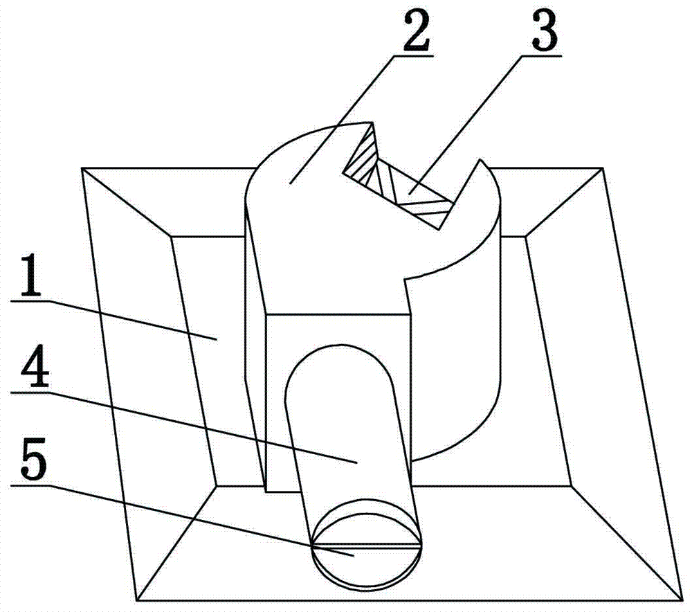
[0015] Such as figure 1 As shown, a substation cable communication wind and moisture exhaust equipment, it includes a cable trench cover plate 1 provided with a vent, an explosion-proof axial flow fan 3 and a ventilation duct 4 arranged on the vent, wherein the explosion-proof axial flow The fan 3 is provided with a sealing cover 2 with an opening at the bottom, and the opening is set corresponding to the ventilation opening. The side wall of the sealing cover 2 is provided with an exhaust hole, and the ventilation duct 4 is arranged on the exhaust hole.

[0016] Based on the above, in order to prevent the cable trench cover 1 from accumulating too much water in rainy days, the cable trench cover 1 includes a connecting plate with a vent on the top and four isosceles trapezoidal side plates, and the four isosceles trapezoidal side plates The side plates are respectively arranged on the edges of the connecting plates, and the isosceles trapezoidal side plates are slightly incli...

Embodiment 2

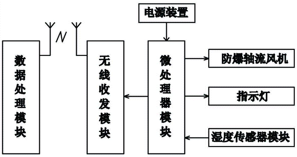
[0020] Such as figure 2 As shown, this embodiment adds a control system on the basis of Embodiment 1, and the control system includes a humidity sensor module, a microprocessor module connected to the humidity sensor, and an indicator light connected to the microprocessor module , a wireless transceiver module, a data processing module with a wireless transceiver module and a power supply unit, the humidity sensor module is arranged at the bottom of the cable trench cover, the microprocessor module is connected to the explosion-proof axial fan, and the wireless transceiver module The module is connected with the microprocessor module, the wireless transceiver module communicates with the data processing module, and the power supply device is respectively connected with the humidity sensor module, the microprocessor module, the indicator light and the explosion-proof Axial fan connection.

[0021] Based on the above, the humidity sensor module is used to collect the humidity ...


PUM


Abstract

The invention provides ventilation and moisture removal equipment for a cable trench of a transformer substation. The equipment comprises a cable trench cover plate with an air vent, an explosion-proof axial flow fan arranged on the air vent and a ventilation pipeline. The cable trench cover plate comprises a connecting plate and four isosceles trapezoid-shaped side plates, wherein an air vent is formed on the top of the connecting plate; and the four isosceles trapezoid-shaped side plates are arranged on the edge of the connecting plate respectively, and are slightly inclined downwards. The axial flow fan is provided with a sealing cover. An opening is formed at the bottom of the sealing cover, and is opposite to the air vent. An air exhaust hole is formed on the sidewall of the sealing cover. The ventilation pipeline is arranged on the air exhaust hole. The ventilation and moisture removal equipment for the cable trench of the transformer substation has the advantages of scientific design, high practicability and good moisture removal effects, and is easy to use.

Description

technical field [0001] The invention relates to a dehumidification device for cable trenches, in particular to a dehumidification device for cable communication wind in a substation. Background technique [0002] At present, there is a lack of dynamic monitoring for cable trenches in most substations and cable interlayers in the lower part of switch cabinets. Due to moisture and other reasons, it is easy to cause corrosion of electrical equipment and protective devices, reduce the insulation strength of equipment, and cause flashover of equipment in substations, etc. Accidents seriously affect the safety of power supply and the healthy operation of equipment. With the development of the information technology era, intelligent substations have been vigorously promoted, and intelligent monitoring of high-voltage electrical equipment has developed rapidly. In order to solve the above existing problems, people have been seeking an ideal technical solution. [0003] In order to...

Claims


Application Information

Patent Timeline
Patent Type & Authority Applications(China)
IPC IPC(8): H02G9/00H02G9/02
Inventor 张耀午刘汉平陈瑞琳
Owner XINYANG POWER SUPPLY OF HENAN ELECTRIC POWER CORP
Why Eureka
Try Eureka