Broken bone section and broken bone model registration method based on maximum common subgraph and bounding box

A technology of the largest common sub-image and bounding box, which is applied in image enhancement, image analysis, image data processing, etc. It can solve the problems that the cross-sectional shapes cannot be roughly matched, the fine registration is inaccurate, and the automatic extraction of cross-sections cannot be realized.

Active Publication Date: 2017-11-03
DALIAN UNIV OF TECH
View PDF8 Cites 10 Cited by
  • Summary
  • Abstract
  • Description
  • Claims
  • Application Information

AI Technical Summary

Problems solved by technology

[0002] At present, the combination of artificial reduction and internal fixation of the injured limb is generally used in fracture surgery. The problems of this method are large trauma, heavy bleeding, and easy to cause complications such as neurovascular injury.
However, according to the two aspects of the angle between the normal vector of the section and the main axis and the sudden change of the normal vector, the section segmentation needs to be manually selected on the model, and the automatic extraction of the section cannot be realized.
[0004] In addition, simply aligning the main axes of the broken bones cannot meet the requirements of pre-registration, and the cross-sectional directions of the broken bones may deviate from each other, and the cross-sectional shapes cannot be roughly consistent, which is likely to cause fine registration errors. Inaccurate

Method used


Image

  • Broken bone section and broken bone model registration method based on maximum common subgraph and bounding box
  • Broken bone section and broken bone model registration method based on maximum common subgraph and bounding box
  • Broken bone section and broken bone model registration method based on maximum common subgraph and bounding box

Examples


Embodiment Construction

[0055] In order to make the purpose, technical solutions and advantages of the embodiments of the present invention more clear, the technical solutions in the embodiments of the present invention are clearly and completely described below in conjunction with the drawings in the embodiments of the present invention:

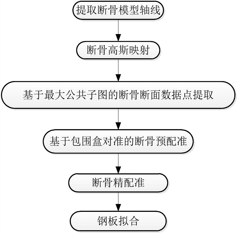
[0056] Such as Figure 1-9 Shown: The registration method of the broken bone section and the broken bone model based on the largest common subimage and the bounding box mainly includes the following steps:

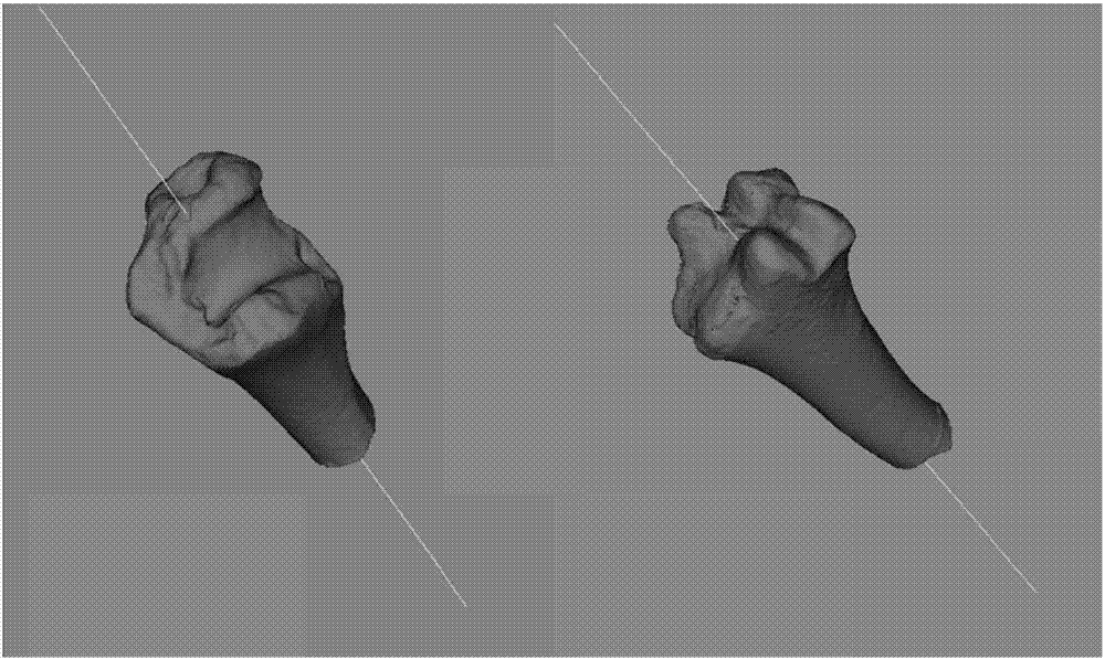
[0057] Fracture Axis Extraction

[0058] This method uses the PCA algorithm to extract the axis of the broken bone. The extraction effect is as figure 2 shown.

[0059] Enter the initial sample matrix. According to the input model, let the model contain a total of n points, and assign the coordinates of these n points to a 3×n matrix, which is the initial sample matrix

[0060] The initial sample matrix is ​​centered. After centering the initial sampl...


PUM


Abstract

The invention discloses a broken bone section and broken bone model registration method based on a maximum common subgraph and a bounding box. The method comprises the following steps of broken bone axis extraction, broken bone Gauss mapping, section point set extraction, broken bone pre-registration and broken bone accurate registration. The step of section point set extraction comprises sub steps: triangular patches whose normal vectors and the broken bone axis are in a certain angle are eliminated and the broken bone model is segmented to two broken bone models, wherein each model comprises a section model containing the broken bone; elimination on triangular patches is carried out on the two broken bones respectively, and four sub models are obtained finally, wherein two are section models; and a section point set for nodes in the four sub models is extracted, each two section motors is compared through a maximum common subgraph algorithm, and a pair of sub models containing the maximum nodes are selected as the two section modes. The step of broken bone pre-registration is to build bounding boxes for the two section models, and the two bounding boxes are aligned in the space to complete pre-registration. The step of broken bone accurate registration is to carry out accurate registration on the two broken bones through an ICP algorithm to complete joint between the two broken bones.

Description

technical field [0001] The invention relates to a method for registering a broken bone section and a broken bone model based on the largest common subgraph and a bounding box. Involves patent classification number G06 Calculation; Calculation; Counting G06T General image data processing or generation G06T7 / 00 Image analysis, such as from bitmap to non-bitmap. Background technique [0002] At present, the combination of artificial reduction and internal fixation of the injured limb is generally used in fracture surgery. The problems of this method are large trauma, heavy bleeding, and easy to cause complications such as neurovascular injury. Therefore, the computer can be used to virtual stitch the broken bone model, so that various geometric parameters of the steel plate can be obtained before the operation. However, there are many problems in the current virtual stitching method of broken bones, such as inaccurate section segmentation, manual operation, inaccurate pre-regi...

Claims


Application Information

Patent Timeline
Patent Type & Authority Applications(China)
IPC IPC(8): G06T7/33
CPCG06T7/344G06T2207/10081G06T2207/30008
Inventor 刘斌刘文鹏张松王明哲张晓慧杨乙乾
Owner DALIAN UNIV OF TECH
Why Eureka
Try Eureka