Rotary self-cleaning type fluted disc switching valve

A switching valve, self-cleaning technology, used in sliding valves, valve details, valve devices, etc., can solve the problems of large leakage of exhaust gas and difficult sealing of wind direction switching valves

Pending Publication Date: 2017-11-07
JIANGSU ZHONGKE MACHINERY
View PDF5 Cites 0 Cited by
  • Summary
  • Abstract
  • Description
  • Claims
  • Application Information

AI Technical Summary

Problems solved by technology

[0003] The purpose of the present invention is to provide a rotary self-cleaning tooth disc switching valve. By improving the structure and sealing structure of the wind switching valve, it can solve the defects that the wind direction switching valve is not easy to seal, and the large amount of exhaust gas leakage affects the purification rate of VOC. Improving the Quality and Efficiency of Waste Gas Purification of Regenerative Combustion Device

Method used


Image

  • Rotary self-cleaning type fluted disc switching valve
  • Rotary self-cleaning type fluted disc switching valve
  • Rotary self-cleaning type fluted disc switching valve

Examples


no. 1 example

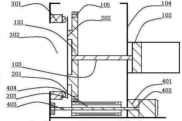
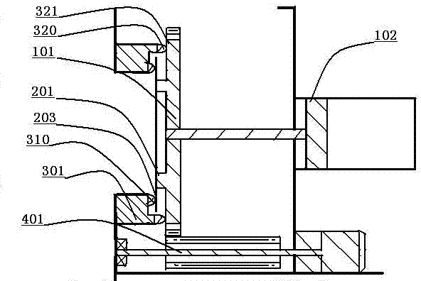
[0022] Such as figure 1 As shown, the rotary self-cleaning toothed plate switching valve includes a toothed plate 101 , a valve plate 201 , a valve seat 301 and a rotating device 401 . The toothed disc 101 is fixedly installed concentrically with the pull rod 103 of the cylinder 102 , and the cylinder 102 is fixed outside the gas distribution box 104 ; the outer wall of the toothed disc 101 is provided with a ring gear 105 . The valve plate 201 is fixedly installed on the inner wall surface 202 of the gear plate 101 . The valve seat 301 is installed on the vent 302 of the gas distribution box 104 , and the valve seat 301 is eccentrically installed with the pull rod 103 of the cylinder 102 . A gear 404 is installed on the transmission shaft 403 of the reduction motor 402 of the rotating device 401 , and the gear 404 is installed in contact with the ring gear 105 of the toothed disc 101 . Such as figure 2 As shown, the sealing wall surface 203 of the valve plate 201 contacts...

no. 2 example

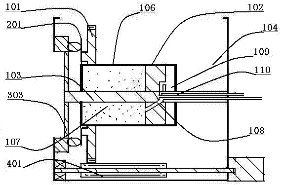
[0025] Such as image 3 As shown, the cylinder 102 is installed inside the gas distribution box 104, and one end of the pull rod 103 of the cylinder 102 is fixed on the inner wall of the gas distribution box 104, and the other end of the pull rod 103 is fixed on the valve seat 301 ring support 303. The toothed plate 101 and the valve plate 201 are fixed on the outer cylinder body 106 of the cylinder 102, the air pipe 108 of the upper cylinder chamber 107 of the cylinder 102 is installed in the inside of the pull rod 103, and the air pipe 110 of the lower cylinder chamber 109 of the cylinder 102 is installed on the inside of the pull rod 103. internal. Such as Figure 4 As shown, the ring disc 101, the valve plate 201 and the valve seat 301 are contacted and sealed to form an annular air-filled chamber 130, and an intake pipe 120 is installed between the annular air-filled chamber 130 and the lower cylinder chamber 109 of the cylinder 102, and the lower cylinder chamber 109 A...


PUM


Abstract

The invention discloses a rotary self-cleaning type fluted disc switching valve. The rotary self-cleaning type fluted disc switching valve comprises a fluted disc, a valve plate, a valve seat and a rotating device. The valve seat and the valve plate are eccentrically installed, a gear of the rotating device drives the fluted disc to rotate, the valve plate and the valve seat are in contact friction to erase away dirt, and automatic cleaning work is achieved under the working condition without a halt; contact surfaces of the valve plate and the valve seat are continuously changed, the problem that sealing is affected by work fatigue deformation of a valve plate of a switching valve is completely solved, and the waste gas purification quality and efficiency of a regenerative combustion device are greatly improved.

Description

technical field [0001] The invention relates to a rotary self-cleaning gear plate switching valve of a regenerative combustion device, in particular to the technical field of a regenerative RTO combustion device for waste gas treatment. Background technique [0002] The current regenerative combustion device RTO heats the organic waste gas discharged from production through heat storage ceramics, and the temperature rises rapidly. Under the action of gas combustion and heating in the furnace, the temperature reaches 680-1050°C, and the VOCs in the organic waste gas are here It is directly decomposed into carbon dioxide and water vapor at high temperature to form odorless high-temperature flue gas, and then flows through the low-temperature regenerative ceramics. The temperature of the exhaust gas and high-temperature flue gas drops significantly, and then heat exchange occurs with other media through the heat recovery system, the temperature of the flue gas is further reduce...

Claims


Application Information

Patent Timeline
Patent Type & Authority Applications(China)
IPC IPC(8): F16K31/12F16K3/02F16K3/30
CPCF16K3/02F16K3/30F16K31/12
Inventor 顾国勋
Owner JIANGSU ZHONGKE MACHINERY
Why Eureka
Try Eureka