Rotary automatic cleaning type switching valve of thermal storage combustion device

An automatic cleaning, regenerative combustion technology, applied in valve devices, cleaning hollow objects, cleaning methods and utensils, etc., can solve the problems of large leakage of exhaust gas and difficult sealing of wind direction switching valves.

Active Publication Date: 2017-09-15
JIANGSU ZHONGKE MACHINERY
View PDF6 Cites 1 Cited by
  • Summary
  • Abstract
  • Description
  • Claims
  • Application Information

AI Technical Summary

Problems solved by technology

[0003] The purpose of the present invention is to provide a rotary automatic cleaning switching valve for a regenerative combustion device. By improving the structure and sealing structure of the wind switching valve, the defects that the wind direction switching valve is not easy to seal and the large amount of exhaust gas leakage affects the purification rate of VOC are solved. , greatly improving the exhaust gas purification quality and efficiency of the regenerative combustion device

Method used


Image

  • Rotary automatic cleaning type switching valve of thermal storage combustion device
  • Rotary automatic cleaning type switching valve of thermal storage combustion device
  • Rotary automatic cleaning type switching valve of thermal storage combustion device

Examples


no. 1 example

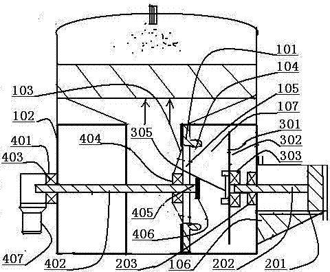
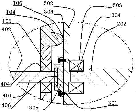
[0027] Such as figure 1 As shown, the rotary automatic cleaning switching valve of the regenerative combustion device includes: a valve seat 101 , a cylinder 201 , a rotary valve plate 301 and a rotary device 401 . The valve seat 101 is installed on the air duct opening 103 of the gas distribution box 102, and the side of the valve seat 101 is provided with an annular sealing port 104, and an annular bracket 105 is installed in the annular sealing port 104. Cylinder 201 is installed on the outer wall support 106 of gas distribution box 102, and the push-pull rod 202 of cylinder 201 stretches in the air channel 107 of gas distribution box 102, and this push-pull rod 202 is installed in the linear bearing seat 203 of air channel 107 wall surfaces. A self-aligning bearing seat 303 is installed on the lower wall of the valve plate 302 of the rotating valve plate 301 , and the connecting shaft head 204 of the push-pull rod 202 is installed in the self-aligning bearing seat 303 . A...

no. 2 example

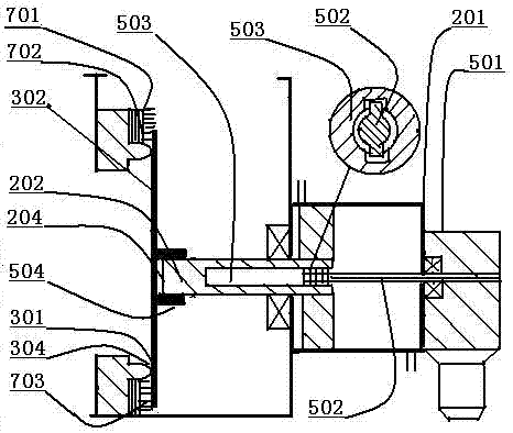
[0030] Such as image 3 As shown, the rotating device and the cylinder are fixedly installed, the cylinder 201 and the cylinder rotating device 501 are fixedly installed, and the transmission rod 502 of the cylinder rotating device 501 is installed in the connecting sleeve 503 inside the push-pull rod 202 . The connecting shaft head 204 of the push-pull rod 202 is fixedly installed in the fixed sleeve 504 of the rotary valve plate 301 . The transmission rod 502 of the cylinder rotating device 501 rotates, driving the push-pull rod 202 and the rotary valve plate 301 to rotate.

[0031] So far, the second embodiment of the present invention, the rotary automatic cleaning switching valve of the regenerative combustion device, has been introduced.

no. 3 example

[0033] In order to improve the cleanliness of the rotary valve plate 301, as Figure 4 As shown, a scraper cleaning device 602 is installed on the support arm surface 601 of the annular support 105, and the elastic scraper 603 of the scraper cleaning device 602 is fixedly installed obliquely with the support arm surface 601 through the pressure plate 604, and the top end of the elastic scraper 603 extends Out of the ring sealing port 104. The elastic scraper 104 deforms after being squeezed by the valve plate 302 , and sticks to the sealing wall 304 of the valve plate 302 . The rotary valve plate 301 rotates, and the elastic scraper 104 removes the dirt on the sealing wall 304 of the valve plate 302 . Such as image 3 As shown, a cleaning device 601 is fixedly installed on the outside or inside wall of the valve seat 101 annular sealing port 104, and a cleaning grinding head 603 is installed in the elastic seat 602 of the cleaning device 601; the rotating valve plate 301 rot...


PUM


Abstract

The invention discloses a rotary automatic cleaning type switching valve of a thermal storage combustion device. The rotary automatic cleaning type switching valve of the thermal storage combustion device comprises a valve seat, a rotary valve plate, a cylinder and a rotary device; the valve seat and the rotary valve plate are installed relatively eccentrically; the rotary device drives the rotary valve plate to rotate; the valve plate eccentrically rotates relative to an annular sealing opening; the annular wall face of the annular sealing opening makes contact with and rubs with the sealing wall face of the valve plate for automatically cleaning away dirt; the rotary automatic cleaning type switching valve conducts automatic cleaning work under the working condition of non-stop; and at the same time, the defect that the fatigue deformation of a valve plate affects the sealing effect is overcome, and the waste gas purifying quality and efficiency of the thermal storage combustion device are substantially improved.

Description

technical field [0001] The invention relates to a rotary automatic cleaning switching valve of a regenerative combustion device, in particular to the technical field of a regenerative (RTO) combustion device for waste gas treatment. Background technique [0002] The current regenerative combustion device (RTO) heats the organic waste gas discharged from the production through the heat storage ceramics, and the temperature rises rapidly. Under the action of gas combustion and heating in the furnace, the temperature reaches 680-1050°C, and the VOCs in the organic waste gas At this high temperature, it is directly decomposed into carbon dioxide and water vapor to form odorless high-temperature flue gas, which then flows through the low-temperature regenerative ceramics. The organic waste gas is decomposed, and the temperature of the high-temperature flue gas itself is greatly reduced. After heat exchange with other media through the heat recovery system, the temperature of the ...

Claims


Application Information

Patent Timeline
IPC IPC(8): F16K1/32F16K1/42F16K31/122B08B9/027
CPCF16K1/32F16K1/42F16K31/122B08B9/027Y02E20/34
Inventor 顾国勋
Owner JIANGSU ZHONGKE MACHINERY
Why Eureka
Try Eureka