A device for cleaning the inner side of the extrusion ring of a mixer

A technology for cleaning devices and extruding rings, which is applied in mixers, mixers with rotating mixing devices, transportation and packaging, etc., can solve problems such as uneven mixing and mixing machine spraying slurry.

Active Publication Date: 2020-10-27
北新建材(苏州)有限公司
View PDF7 Cites 0 Cited by
  • Summary
  • Abstract
  • Description
  • Claims
  • Application Information

AI Technical Summary

Problems solved by technology

[0003] Aiming at the problem in the prior art that the material layer on the lower side of the extrusion ring causes the mixer to spray material or the slurry is not evenly stirred, the purpose of the present invention is to provide a device for cleaning the accumulated material inside the extrusion ring of the mixer

Method used


Image

  • A device for cleaning the inner side of the extrusion ring of a mixer
  • A device for cleaning the inner side of the extrusion ring of a mixer

Examples


Embodiment 1

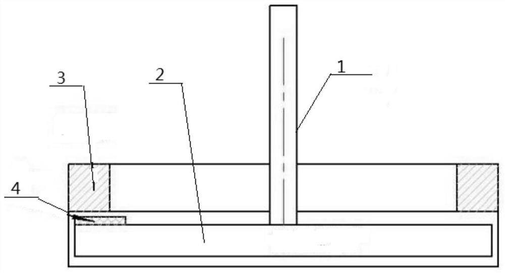
[0018] Example 1 as figure 1 As shown, a device for cleaning the accumulated material inside the extrusion ring of a mixer includes a mixer rotor, a scraper 4 and an extrusion ring 3. The mixer rotor is an integrated structure formed by vertically connecting the rotating shaft 1 along the center of the turntable 2. The end face of the turntable 2 and the end face of the extrusion ring 3 are parallel and coaxially opposed to each other, and the cavity formed between the two is a blanking gap. The scraper 4 is fixed on the top edge of the turntable 2 and is located at Below the squeeze ring 3 , the scraper 4 is fastened on the turntable 2 of the mixer rotor by screws, and the scraper 4 is arranged facing the squeeze ring 3 with a predetermined gap between the squeeze ring 3 .

[0019] The main working principle is as follows: the cleaning device is mainly composed of a chrome-plated stainless steel plate with a size of 3cm*10cm*3mm, such as figure 1 As shown, the scraper 4 is f...

Embodiment 2

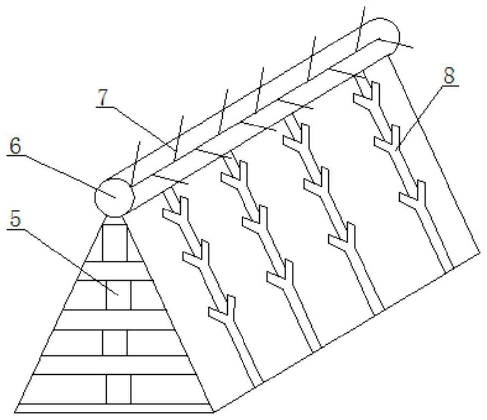
[0021] On the basis of Example 1, different from Example 1, such as figure 2 As shown, the scraper 4 is arranged as a horizontal triangular prism structure, and its side wall is set close to the surface of the turntable 2. The scraper 4 is fixedly installed on the outer edge of the turntable 2, and the extension direction of the scraper 3 extends along the radius of the turntable 2. The direction is set, and the special structure of the scraper 4 makes the walls on both sides form a certain slope, which has the function of diverting flow and preventing materials from sticking, and forms a good diversion effect during the rotation process.

[0022] The inside of the scraper 4 is provided with a "convex"-shaped support frame 5 from top to bottom. The support frame 5 is arranged from top to bottom along the taper, and the support stability is strong, which prevents the scraper 4 from being deformed by the impact force, enhances the cutting force of the scraper 4, and prolongs th...

Embodiment 3

[0026] On the basis of Embodiment 1, different from Embodiment 1, the turntable 2 is arranged downward in a certain arc from the center position to form a bamboo hat structure. The slope surface has flow conductivity, so that the material can be quickly and evenly dispersed from the blanking gap under the action of centripetal force.

[0027] The upper surface of the turntable 2 is concentrically arranged with diversion grooves arranged in a circular shape. The diversion grooves are configured as cylindrical structures protruding from the upper surface of the turntable. The height of the diversion grooves gradually decreases from the center to the outside. The setting of the diversion groove enables the material to be evenly dispersed along the surface of the turntable 2 under the action of the rotating centripetal force, which improves the uniformity of material dispersion.


PUM


Abstract

The invention discloses a material accumulation cleaning device inside the extrusion ring of a mixer. The rotor of the mixer is an integrated structure in which the rotating shaft is vertically connected along the center of the turntable. The turntable is arranged above the extrusion ring and the two are coaxial. set, and the cavity formed between the two is the blanking gap, the scraper is fixed on the top edge of the turntable and is located below the extrusion ring, the scraper is set directly against the extrusion ring and is connected to the extrusion ring There is a certain gap between them. When the rotor of the mixer rotates, the scraper is attached to the rotor. With the rotation of the rotor, a dynamic scraper is formed to clean the gap between the extrusion ring and the rotor, and realize the automatic cleaning of the inner side of the extrusion ring, which can ensure The gap is always at a fixed size, which eliminates the side effects caused by material accumulation in the inner ring. It is convenient for observation and maintenance, and the equipment is easy to install and convenient for subsequent cleaning operations. At the same time, due to the special structure of the scraper, it has high hardness and good wear resistance, which can increase the service life of the scraper.

Description

technical field [0001] The invention belongs to the technical field of gypsum board production equipment, and in particular relates to a material accumulation cleaning device inside an extrusion ring of a mixer. Background technique [0002] During the feeding process of the mixer, the stirred slurry is thrown out through the gap between the extrusion ring and the rotor, thus completing the feeding process. Due to internal pressure and gypsum material problems, a thin layer of material will be formed on the lower side of the extrusion ring and adhere to the inner side of the extrusion ring. Once this material layer is formed, the blanking gap of the mixer will become smaller, resulting in the situation that the slurry in the mixer cannot be smoothly discharged due to the reduction of the outlet area, resulting in the phenomenon of spraying of the mixer or uneven mixing of the slurry. . This requires a mechanism that can clean up the material layer at this place at any time...

Claims


Application Information

Patent Timeline
Patent Type & Authority Patents(China)
IPC IPC(8): B08B1/04B01F15/00B01F7/00
CPCB08B1/005B08B1/04B01F27/00B01F35/123
Inventor 梁云飞刘晨刘伟周继明王浩然向清昌邱珂王支公郭臣明朱敏
Owner 北新建材(苏州)有限公司
Why Eureka
Try Eureka