Transformer with built-in cooling structure and capable of synchronously removing moisture

A cooling structure and transformer technology, applied in the field of transformers, can solve the problems of hidden dangers of transformer safety, damaged parts, easy infiltration of water stains during cleaning work, etc., and achieve the effect of improving service life and improving practicability.

Inactive Publication Date: 2021-03-16
龚爱珍
View PDF0 Cites 0 Cited by
  • Summary
  • Abstract
  • Description
  • Claims
  • Application Information

AI Technical Summary

Problems solved by technology

[0006] The purpose of the present invention is to provide a transformer with a built-in cooling structure that can simultaneously remove moisture, so as to solve the problem that the inner side of the device is prone to generate a large amount of heat during the long-term operation proposed in the background technology, resulting in a greater degree of heat exposure Under the environment, it is very easy to cause damage to the internal parts of the device. It does not have a good built-in heat dissipation and cooling structure, so that the overall service life of the device cannot be guaranteed. When it is affected by weather such as rain, its surface is easy to accumulate a large amount of Water stains, which cannot be cleaned automatically, cause water stains to easily penetrate into the interior of the device, thus causing safety hazards to the transformer

Method used


Image

  • Transformer with built-in cooling structure and capable of synchronously removing moisture
  • Transformer with built-in cooling structure and capable of synchronously removing moisture
  • Transformer with built-in cooling structure and capable of synchronously removing moisture

Examples


Embodiment Construction

[0027] The following will clearly and completely describe the technical solutions in the embodiments of the present invention with reference to the accompanying drawings in the embodiments of the present invention. Obviously, the described embodiments are only some, not all, embodiments of the present invention. Based on the embodiments of the present invention, all other embodiments obtained by persons of ordinary skill in the art without making creative efforts belong to the protection scope of the present invention.

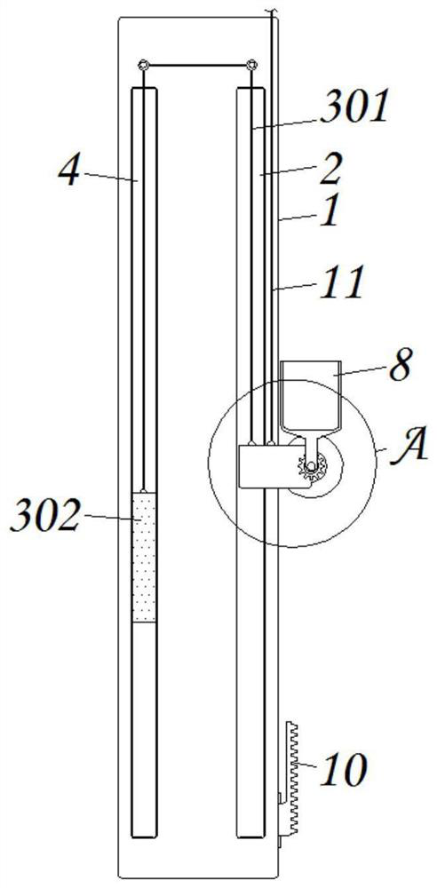
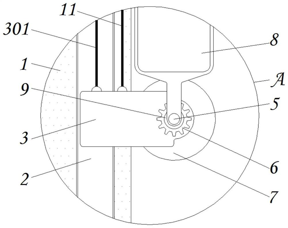
[0028] see Figure 1-6 , the present invention provides a technical solution: a transformer with a built-in cooling structure and synchronous removal of moisture, including a transformer body 1, a first chute 2, a movable part 3, a second chute 4, a connecting shaft 5, and a first gear 6. Cleaning part 7, liquid collecting part 8, first torsion spring 9, fixed rack 10, first pull cord 11, protective part 12, dustproof gauze 13, movable fan blade 14, transmissi...


PUM


Abstract

Disclosed is a transformer with a built-in cooling structure and capable of synchronously removing moisture. The transformer comprises a transformer body, a connecting shaft, a liquid collecting piece, a dustproof gauze element and a reset spring, a first sliding groove is formed in the outer side of the transformer body, a movable piece is installed at the outer end of the first sliding groove ina nested mode, the movable piece is connected with the outer side of the transformer body, a second sliding groove is formed in the rear side edge end of the transformer body, a connecting shaft is installed at the outer end of the movable piece in a penetrating mode, a first gear is fixedly connected to the outer side of the connecting shaft, a cleaning piece is connected to the outer side of the middle end of the connecting shaft in an adhesive mode, and a heat conduction piece is installed on the inner side of the installation frame in a nested mode. According to the transformer with the built-in cooling structure and capable of synchronously removing moisture, in rain days, when the amount of rainwater accumulated in a liquid collecting piece reaches a certain degree, a cleaning pieceis pushed to move downwards along the outer surface of the transformer body in an attached mode, and then automatic cleaning work of water spots on the surface of the transformer is achieved.

Description

technical field [0001] The invention relates to the technical field of transformers, in particular to a transformer with a built-in cooling structure and capable of synchronously removing moisture. Background technique [0002] With the continuous development of my country's electric power industry, all kinds of power equipment are widely used, among which transformers have gradually become more common power conversion equipment, which can be seen everywhere in various places, and transformers use electromagnetic induction The device that changes the AC voltage based on the principle is a bridge for power flow, but the existing transformers still have certain defects, such as: [0003] 1. During the long-term operation of the existing transformer, the inside of the device is prone to generate a large amount of heat, which leads to the occurrence of damage to the internal parts of the device when it is heated to a large extent. It does not have a good Built-in heat dissipatio...

Claims


Application Information

Patent Timeline
Patent Type & Authority Applications(China)
IPC IPC(8): H01F27/02H01F27/08H01F27/22H01F27/00B08B1/00
CPCB08B1/008H01F27/00H01F27/022H01F27/085H01F27/22
Inventor 龚爱珍
Owner 龚爱珍
Why Eureka
Try Eureka