Method and apparatus for evaluating an ultrasonic weld junction

A fusion line and ultrasonic technology, used in the generation of ultrasonic/sonic/infrasonic waves, the use of sonic/ultrasonic/infrasonic waves to analyze solids, and the use of sonic/ultrasonic/infrasonic waves for material analysis, etc. question

Active Publication Date: 2017-11-10
GM GLOBAL TECH OPERATIONS LLC
View PDF8 Cites 5 Cited by
  • Summary
  • Abstract
  • Description
  • Claims
  • Application Information

AI Technical Summary

Problems solved by technology

The process capability of the ultrasonic welding process that forms the inte

Method used


Image

  • Method and apparatus for evaluating an ultrasonic weld junction
  • Method and apparatus for evaluating an ultrasonic weld junction
  • Method and apparatus for evaluating an ultrasonic weld junction

Examples


Embodiment Construction

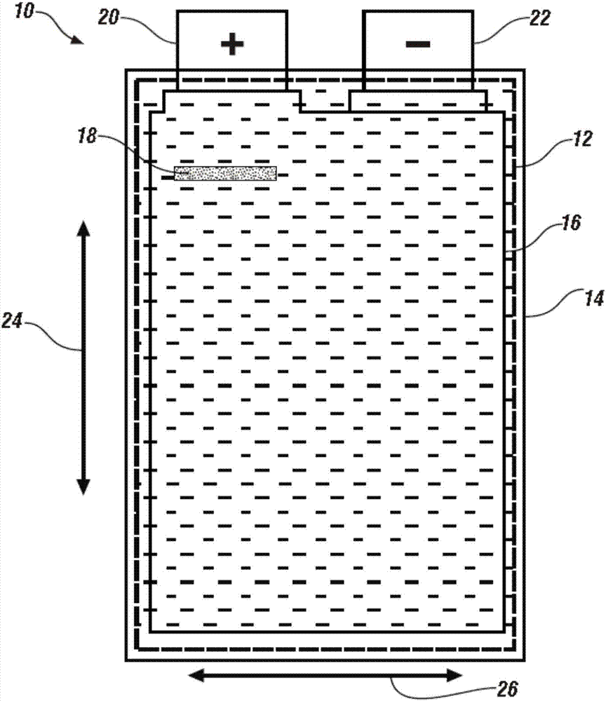
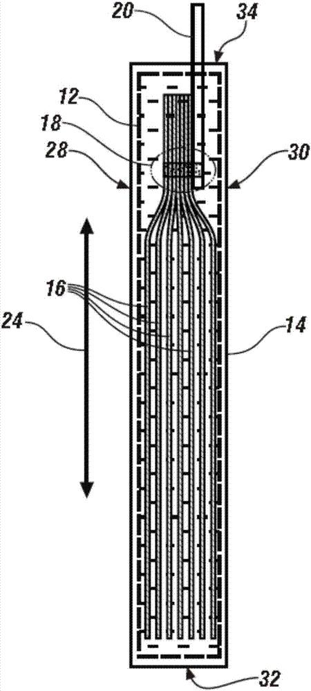
[0011] Referring now to the drawings (which are provided only to illustrate certain exemplary embodiments and not to limit these exemplary embodiments), Figure 1A and 1B A front view and a corresponding side view of a selection element of an individual battery cell 10 are each schematically shown. Like reference numerals designate like or corresponding components throughout the several views. Those of ordinary skill in the art will understand that terms such as "horizontal", "vertical", "above", "below", "upward", "downward", "top" and "bottom" The drawings are used descriptively and do not represent limitations on the scope of the invention as defined in the appended claims. The term "end effector" is defined as a device which can be controlled to perform a predetermined task in response to a control command, and which can also be actuated mechanically, electromechanically and pneumatically or can employ another actuation system.

[0012] In one embodiment, battery cell 10...


PUM


Abstract

A method and a test fixture for evaluating a battery cell composed of a cell body having a plurality of electrode foils, a positive terminal and a negative terminal, wherein the positive terminal and the negative terminal are each joined to the cell body at weld junctions. This includes retaining the cell body of the battery cell in a first clamping device. The terminal is grasped in a terminal gripper. A dynamic stress end effector coupled to the terminal gripper applies a vibrational excitation load to the terminal. A static stress end effector applies a static load to the terminal. Integrity of the weld junction is evaluated based upon the applied static load.

Description

technical field [0001] The invention relates to cells of a battery pack and their weld lines. Background technique [0002] A battery pack typically includes a plurality of rechargeable battery cells connected in series or parallel to store and supply electrical power to an electrical distribution system. Each battery cell includes a plurality of electrode foils having alternately placed positively charged portions and negatively charged portions. The electrode foils are separated by a separator material and packaged in a sealed outer bag filled with an electrolyte solution. Separator materials (eg, polyethylene and / or polypropylene films) help prevent short circuits from occurring while allowing free charge transfer between the electrode foils. [0003] The positive and negative terminals each extend a short distance outside the sealed bag of each battery cell. The positively charged portions of the electrode foils are ultrasonically welded together and welded to the pos...

Claims


Application Information

Patent Timeline
IPC IPC(8): G01N3/00G01N3/04
CPCG01N3/00G01N3/04G01N2203/0069G01N2203/0236G01N2203/0296G01N2203/04B23K20/10G01N29/045G01N2291/0258B23K31/125B23K2101/38G01R31/3865G01N2203/0073G01N3/08G01N29/04G01N29/34G01N29/4445G01N2291/025
Inventor W·W·蔡D·查克拉博蒂Q·林J·M·穆特A·奥托曼诺T·J·林克
Owner GM GLOBAL TECH OPERATIONS LLC
Why Eureka
Try Eureka