Display method and display device

A display method and display device technology, which can be applied to static indicators, cathode ray tube indicators, instruments, etc., and can solve problems such as insufficient computing power and difficult costs

Active Publication Date: 2020-10-30
PANASONIC INTELLECTUAL PROPERTY CORP OF AMERICA
View PDF5 Cites 0 Cited by
  • Summary
  • Abstract
  • Description
  • Claims
  • Application Information

AI Technical Summary

Problems solved by technology

However, there are also home appliances that have insufficient computing power in terms of communication functions, or home appliances that are difficult to implement communication functions in terms of cost, etc.

Method used


Image

  • Display method and display device
  • Display method and display device
  • Display method and display device

Examples


Embodiment approach 1

[0391] Embodiment 1 will be described below.

[0392] (Observation of brightness of light emitting part)

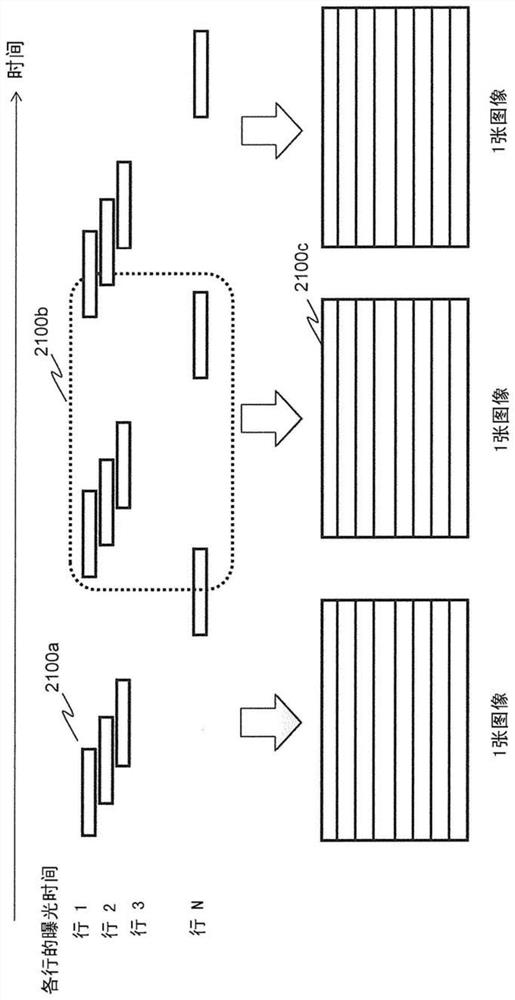
[0393] There is proposed an imaging method that does not expose all imaging elements at the same timing when capturing one image, but starts / stops exposure at different timings for each imaging element. Fig. 1 is an example in which imaging elements arranged in a row are exposed at the same time, and the exposure start timings are shifted in order of the row from the nearest to the farthest to take an image. Here, it is called an exposure line of an imaging element exposed at the same time, and a row of pixels on an image corresponding to the imaging element is called a bright line.

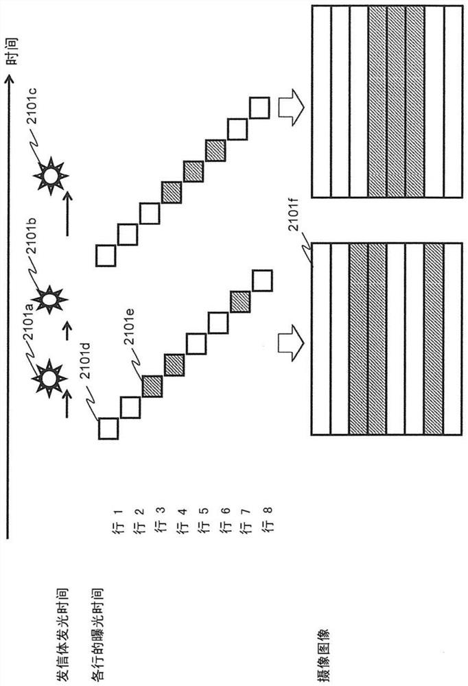
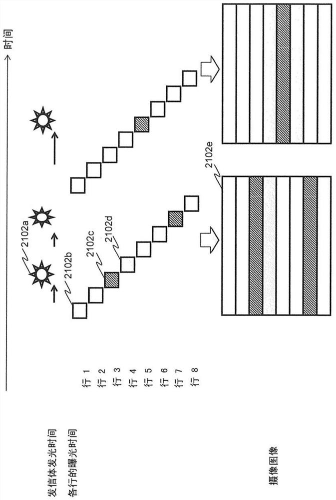
[0394] When using this imaging method to image a flickering light source on the entire surface of the imaging element, if figure 2 In this way, bright lines (lines of brightness and darkness of pixel values) along the exposure line are generated on the captured image. By recognizing the ...

Embodiment approach 2

[0427] In this embodiment, each application example using a receiver such as a smartphone as the information communication device K90 of the first embodiment and a transmitter that transmits information as a blinking pattern of a light source such as LED and / or organic EL will be described.

[0428] In the following description, the normal photography mode or photography in the normal photography mode is referred to as normal photography, and the visible light communication mode or photography in the visible light communication mode is referred to as visible light photography (visible light communication). In addition, intermediate mode imaging may be used instead of normal imaging and visible light imaging, and intermediate images may be used instead of composite images described later.

[0429] Figure 7 It is a diagram showing an example of the imaging operation of the receiver of the present embodiment.

[0430] The receiver 8000 switches the shooting mode between normal ...

Embodiment approach 3

[0505] In this embodiment, each application example using a receiver such as a smart phone and a transmitter that transmits information as a blinking pattern of LED or organic EL in Embodiment 1 or 2 described above will be described.

[0506] Figure 26 It is a diagram showing an example of processing operations of the receiver, the transmitter, and the server according to the third embodiment.

[0507] For example, the receiver 8142 configured as a smartphone acquires position information indicating its own position, and transmits the position information to the server 8141 . In addition, the receiver 8142 obtains position information when receiving other signals, for example, using GPS or the like. The server 8141 transmits to the receiver 8142 a list of IDs associated with the positions indicated by the position information. In the ID list, for each ID such as "abcd", the ID and information associated with the ID are included.

[0508] The receiver 8142 receives a signa...


PUM


Abstract

The present invention provides a display method and a display device capable of displaying useful images to a user. The display method is a display method for displaying images on the display device. The image sensor obtains the captured display image and the image for decoding (SL11) by capturing the object to be photographed, and obtains the light ID by decoding the image for decoding (SL12). Send to the server (SL13), obtain the AR image and identification information corresponding to the light ID from the server (SL14), identify the area corresponding to the identification information in the captured and displayed image as the target area (SL15), and identify the target area in the target area The captured display image superimposed on the AR image is displayed (SL16).

Description

technical field [0001] The present invention relates to a display method, a display device, a recording medium, and the like. Background technique [0002] In recent home networks, in addition to the cooperation of AV home appliances by IP (Internet Protocol) connection under Ethernet (registered trademark) or wireless LAN (Local Area Network), there is also a power consumption corresponding to environmental problems. The home energy management system (HEMS) that has functions such as power ON / OFF from outside the house promotes the introduction of a home appliance collaboration function that connects various home appliances to the network. However, there are home appliances that have insufficient computing power in terms of having a communication function, or home appliances that are difficult to implement a communication function in terms of cost. [0003] In order to solve such a problem, Patent Document 1 describes that in an optical space transmission device that uses ...

Claims


Application Information

Patent Timeline
Patent Type & Authority Patents(China)
IPC IPC(8): H04N21/4223G06T19/00H04B10/116H04N21/431G06V10/25
CPCH04B10/116H04N21/4223G06F3/1454G09G3/346G09G5/14H04N21/2393H04N21/44218H04N21/4722G09G2370/04G09G2370/042G09G2370/10G09G2370/16G06F3/011G06F3/013G06F3/04883G06F3/04847G06F3/04842H04W4/80G06F3/147G09G3/001G09G2360/144G09G2370/022G09G2370/06G09G2370/18G09G2380/10G06Q30/0241G06F3/012G06V20/20G06V10/25H04N13/332H04N13/361G02B27/017H04N21/42218H10K50/11G02B27/646G11C11/418G11C11/419
Inventor 青山秀纪大岛光昭
Owner PANASONIC INTELLECTUAL PROPERTY CORP OF AMERICA
Why Eureka
Try Eureka