Touch panel and display device

A touch panel and touch electrode technology, which is applied in the fields of instruments, computing, electrical and digital data processing, etc., can solve the problems of widening the frame, unfavorable narrow frame realization, etc., and achieve the effect of reducing parasitic capacitance

Active Publication Date: 2017-11-17
SHANGHAI TIANMA MICRO ELECTRONICS CO LTD
View PDF12 Cites 15 Cited by
  • Summary
  • Abstract
  • Description
  • Claims
  • Application Information

AI Technical Summary

Problems solved by technology

[0005] Since each touch sensing electrode RE extends along the second direction D2, each touch sensing electrode line RL needs to be wired in the border areas on both sides of the touch device, that is, both sides of the touch device need to be reserved A frame area with a certain width (for example, hundreds of microns) is used for wiring, which causes the frames on both sides of the touch device to become wider, which is not conducive to the realization of a narrow frame

Method used


Image

  • Touch panel and display device
  • Touch panel and display device
  • Touch panel and display device

Examples


Embodiment Construction

[0028] The application will be further described in detail below with reference to the drawings and embodiments. It can be understood that the specific embodiments described here are only used to explain the related invention, but not to limit the invention. In addition, it should be noted that, for ease of description, only the parts related to the invention are shown in the drawings.

[0029] It should be noted that the embodiments in the application and the features in the embodiments can be combined with each other if there is no conflict. Hereinafter, the present application will be described in detail with reference to the drawings and in conjunction with embodiments.

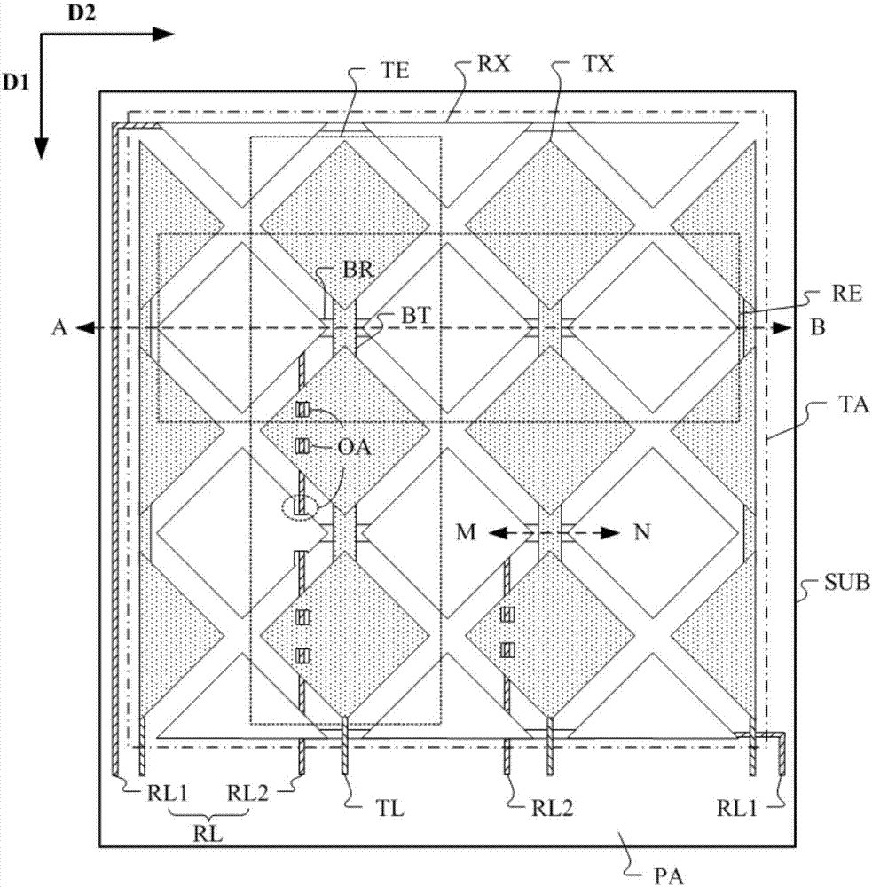
[0030] Figure 2A A schematic diagram of a touch panel according to an embodiment of the present application is shown.

[0031] Such as Figure 2A As shown, the touch panel may include a substrate SUB, a plurality of first touch electrode lines RL, and a plurality of second touch electrode lines TL. Wherein, ...


PUM


Abstract

The invention discloses a touch panel and a display device. The touch panel comprises a plurality of first touch electrodes which are arranged at a base touch area and distributed in the first direction, a plurality of second touch electrodes which are distributed in the second direction, a plurality of first touch electrode wires and a plurality of second touch electrode wires, wherein at least part of each first touch electrode wire is arranged in the touch area; the first touch electrodes and / or the second touch electrodes are provided with opening areas; orthographic projections, on a base, of the first touch electrode wires, are overlapped with the orthographic projections, on the base, of the opening areas. According to the abovementioned scheme, the touch panel has the advantages that the first touch electrodes and / or the second touch electrodes are provided with the opening areas, and at least part of each first touch electrode wire is arranged in the touch area, so that the side frame areas in two sides of the touch panel can be reduced, and as a result, narrow side frames can be realized; in addition, the orthographic projections, on a base, of the first touch electrode wires, are overlapped with the orthographic projections, on the base, of the opening areas, so that parasitic capacitance between the first touch electrode wires and the second touch electrodes can be reduced.

Description

Technical field [0001] This application generally relates to the field of display technology, and in particular to a touch panel and a display device. Background technique [0002] With the development of touch technology, capacitive touch devices have been widely used in electronic devices such as mobile phones, tablet computers, computer monitors, and digital cameras. According to the detection method, capacitive touch devices can be divided into self-capacitive touch devices and mutual capacitive touch devices. [0003] In a mutual-capacitive touch device, the touch function is mainly realized by two touch electrode layers (for example, a touch drive electrode layer and a touch sensing electrode layer), where each layer has multiple touch electrode layers. The touch electrodes are arranged in parallel, and the extension directions of the two layers of touch electrodes intersect. Apply a touch excitation signal to each touch electrode (touch drive electrode) on one of the touch...

Claims


Application Information

Patent Timeline
Patent Type & Authority Applications(China)
IPC IPC(8): G06F3/044G06F3/041
CPCG06F3/0412G06F3/044G06F2203/04103G06F2203/04111G06F2203/04112G06F3/04164G06F3/0443G06F3/0446G06F3/0448
Inventor 谢亮丁洪杨康
Owner SHANGHAI TIANMA MICRO ELECTRONICS CO LTD
Why Eureka
Try Eureka