Pneumatic bending machine

A bending machine and cylinder technology, applied in the field of bending machines, can solve the problems of long bending time of workpieces, inconvenient operation, and long bending time, etc., to improve bending quality, shorten bending time, and facilitate operation Effect

Pending Publication Date: 2017-11-21
宿迁威生金属制品厂
View PDF4 Cites 0 Cited by
  • Summary
  • Abstract
  • Description
  • Claims
  • Application Information

AI Technical Summary

Problems solved by technology

[0002] At present, the material used to make the oven insulation rack is a light-weight refractory material, which has the characteristics of light weight, high temperature resistance and good heat insulation performance, but the insulation rack is not convenient to bend, and the bending time is long, especially complicated. The bending structure requires multiple bending, the bending time of the workpiece is long, and the operation is inconvenient

Method used


Image

  • Pneumatic bending machine
  • Pneumatic bending machine
  • Pneumatic bending machine

Examples


Embodiment Construction

[0011] The preferred embodiments of the present invention are given below in conjunction with the accompanying drawings to describe the technical solution of the present invention in detail.

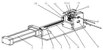
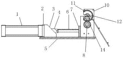
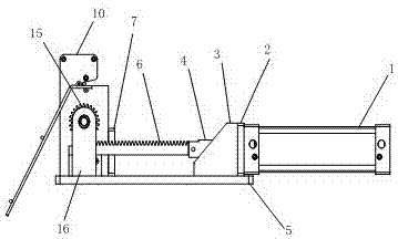
[0012] Such as Figure 1 to Figure 3 As shown, the pneumatic bending machine of the present invention includes a cylinder 1, a cylinder flange 2, a cylinder brace 3, a rack connector 4, a table panel 5, a rack 6, a reinforcement plate 7, a main shaft 8, and a secondary gear cover plate 10. Secondary gear 11, secondary gear fixed shaft 12, bending cutter head 13, transmission gear 14, driving gear 15, main shaft bracket 16, cylinder flange 2 is installed on one side of cylinder 1, cylinder brace 3 is fixed On the other side of the cylinder flange 2, the cylinder flange 2, the cylinder brace 3, the reinforcement plate 7, the secondary gear cover plate 10, and the main shaft bracket 16 are all fixed on the joint plate 5, and one end of the rack 6 passes through the gear The bar connector 4...


PUM


Abstract

The invention discloses a pneumatic bending machine. The machine comprises a pneumatic, etc., wherein a pneumatic flange is mounted at one side of the cylinder; a cylinder inclination supporting part is fixed to the other side of the cylinder flange; the cylinder flange, the cylinder inclination supporting part, a reinforcing plate, a two-stage gear cover plate and a main shaft support are fixed to a combining panel; one end of a rack is connected to the cylinder through a rack connector, and the other end of the rack is engaged with a driving gear; a main shaft passes through a transmission gear and the driving gear and is mounted on the main shaft support; at least one bending product passes through the two-stage gear cover plate; a two-stage gear is mounted between the two-stage gear cover plate and a two-stage gear fixing shaft; a bending cutter head is positioned above the transmission gear and is fixed to the two-stage gear. With the adoption of the pneumatic bending machine, the bending is automatically carried out, so that the time of bending a workpiece is reduced, and the operation is convenient.

Description

technical field [0001] The invention relates to a bending machine, in particular to a pneumatic bending machine. Background technique [0002] At present, the material used to make the oven insulation rack is a light-weight refractory material, which has the characteristics of light weight, high temperature resistance and good heat insulation performance, but the insulation rack is not convenient to bend, and the bending time is long, especially complicated. The bending structure requires multiple bending, the bending time of the workpiece is long, and the operation is inconvenient. Contents of the invention [0003] The technical problem to be solved by the present invention is to provide a pneumatic bending machine, which realizes automatic bending, can shorten the bending time of workpieces, and is easy to operate. [0004] The present invention solves the above-mentioned technical problems through the following technical solutions: a pneumatic bending machine, which i...

Claims


Application Information

Patent Timeline
Patent Type & Authority Applications(China)
IPC IPC(8): B21D11/00B21D11/22
CPCB21D11/00B21D11/22
Inventor 钱春宇陈帅张克宽
Owner 宿迁威生金属制品厂
Why Eureka
Try Eureka