Micro-wave oven

A technology of microwave oven and top plate, applied in the field of microwave oven, can solve the problems of increasing material cost and the like

Active Publication Date: 2018-11-27
GUANGDONG MIDEA KITCHEN APPLIANCES MFG CO LTD +1
View PDF7 Cites 0 Cited by
  • Summary
  • Abstract
  • Description
  • Claims
  • Application Information

AI Technical Summary

Problems solved by technology

However, the protection structure requires more partitions to surround, which increases the material cost

Method used


Image

  • Micro-wave oven
  • Micro-wave oven
  • Micro-wave oven

Examples


Embodiment Construction

[0035] Specific embodiments of the present invention will be described in detail below in conjunction with the accompanying drawings. It should be understood that the specific embodiments described here are only used to illustrate and explain the present invention, and are not intended to limit the present invention.

[0036] In the present invention, the end of the microwave oven with the door is defined as the front end, and the other end is defined as the rear end.

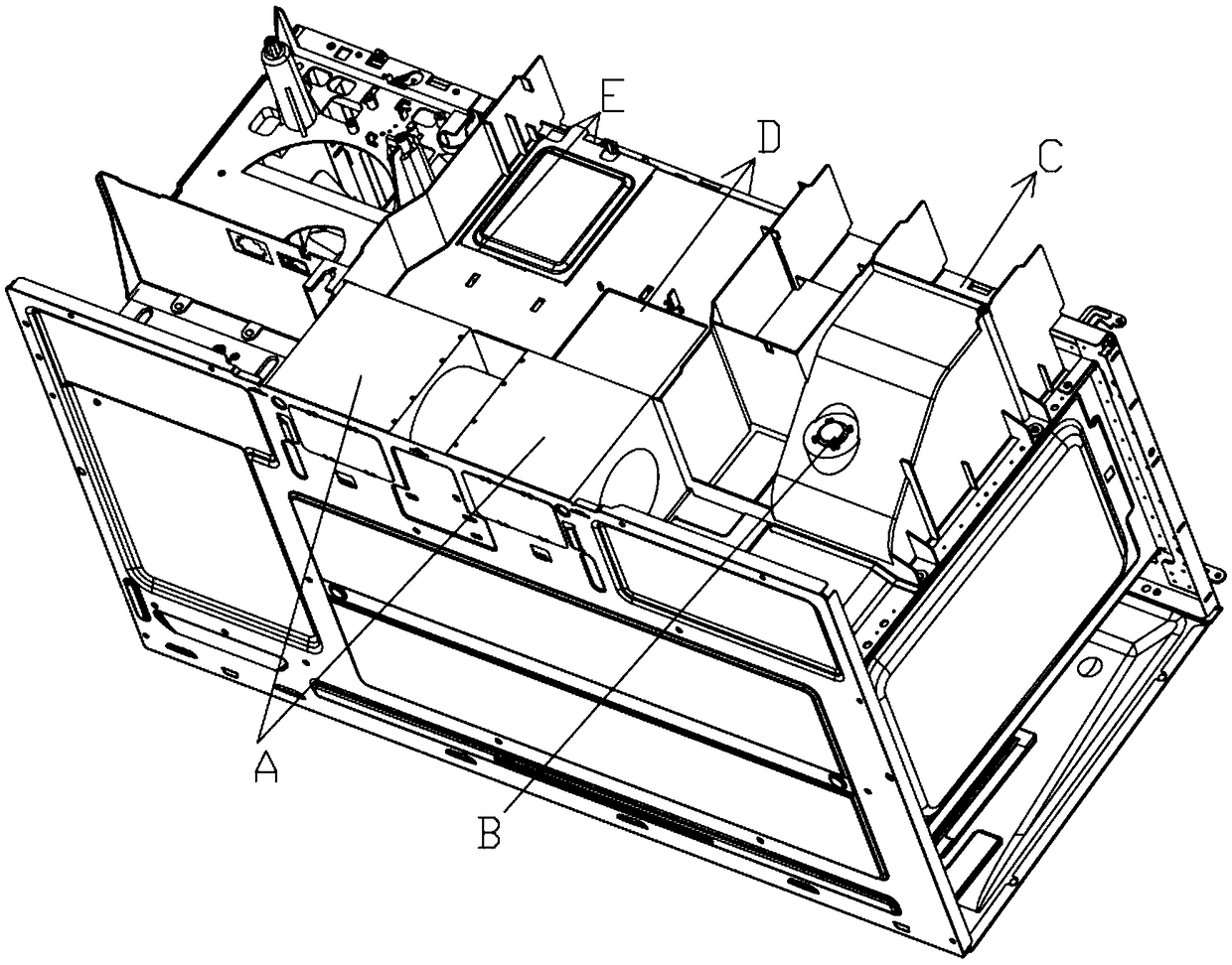
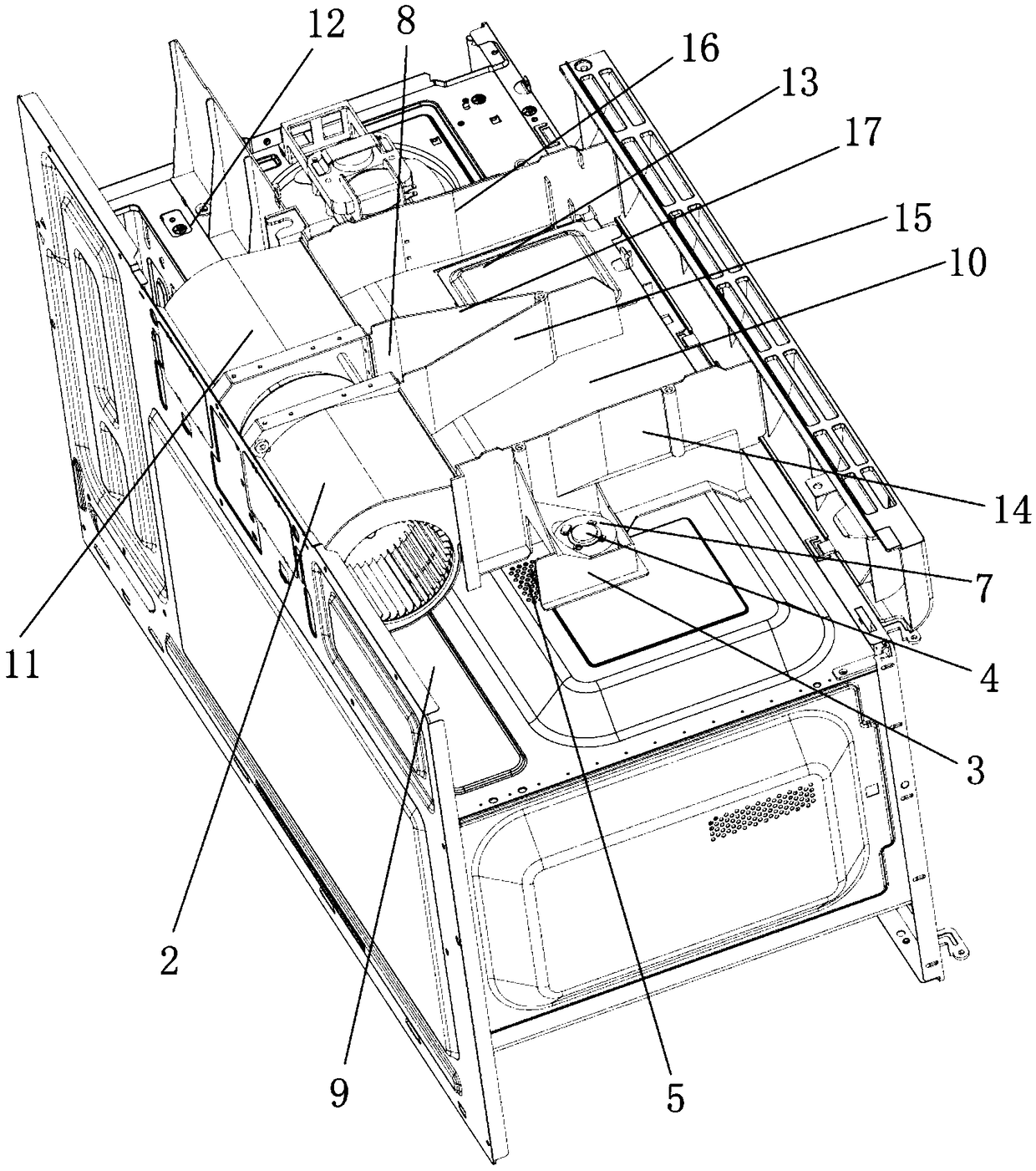
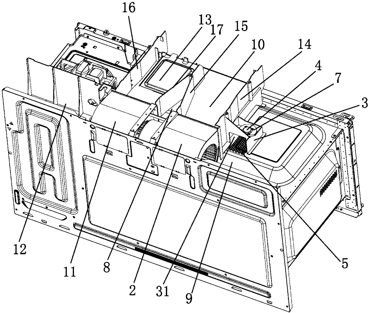
[0037] The present invention provides a microwave oven, comprising a top plate 1 and a steam blower 2 on the top plate 1, the steam blower 2 is located in the middle of the rear of the top plate 1, and the top plate 1 is provided with a The first air inlet channel 9 and the first air exhaust channel 10 connected by the fan 2, the first air inlet channel 9 extends laterally from the steam fan 2 to one side of the top plate 1, and the first air exhaust channel The channel 10 extends from the steam fan to the fro...


PUM


Abstract

The invention relates to the field of household appliances and discloses a microwave oven. The microwave oven comprises a top plate (1) and a steam draught fan (2) arranged on the top plate (1). The steam draught fan (2) communicates with a first intake channel (9). The top plate (1) is provided with an installation portion which is provided with a first opening (31) and located on the front side of the first intake channel (9). A humidity sensor (4) is arranged in the installation portion. An inclined plate (6) is connected between side plates (3) and the top plate (1). The inclined plate (6) forms a second opening (61), the second opening (61) allows a steam circulation path to be formed between the first opening (31) and the humidity sensor (4). By the adoption of the technical scheme, the inclined plate with the opening is arranged in the installation portion, so that steam in the installation portion can be influenced by suction airflow of the draught fan less, a top seal structure of the installation portion can be omitted, and the material cost is less.

Description

technical field [0001] The invention relates to household appliances, in particular to a microwave oven. Background technique [0002] The microwave oven with hood function can suck and discharge smoke, and the upper part of its cavity is provided with a wind guide cover. The air guide hood is divided into a plurality of air ducts by partitions to discharge water vapor from the cavity and smoke from the stove. [0003] In order to detect the humidity in the cavity and then judge the heating state of the food, etc., the microwave oven is also provided with a humidity sensor. The humidity sensor is generally set at the exhaust hole in the air duct, which detects the humidity in the cavity by detecting the water vapor discharged from the exhaust hole, that is, the water vapor, etc. is discharged from the exhaust hole and passes through the humidity sensor. Its humidity is detected and then discharged through the air duct. [0004] like figure 1 As shown, there are two fans ...

Claims


Application Information

Patent Timeline
Patent Type & Authority Patents(China)
IPC IPC(8): F24C7/02F24C7/08H05B6/64
CPCF24C7/08H05B6/6458
Inventor 朱模谭洪力
Owner GUANGDONG MIDEA KITCHEN APPLIANCES MFG CO LTD
Why Eureka
Try Eureka