Measuring cylinder and measuring glass overlook device

A technology for measuring cups and measuring cylinders, which is applied in the field of measuring cylinders and measuring cups, and can solve the problems of inconvenient side-view readings.

Active Publication Date: 2017-11-21
SHANGHAI INSTITUTE OF TECHNOLOGY
View PDF6 Cites 0 Cited by
  • Summary
  • Abstract
  • Description
  • Claims
  • Application Information

AI Technical Summary

Problems solved by technology

[0004] The present invention aims at the long-standing problem of inconvenient side-view readings when conventional measuring cups and measuring cylinders are used to measure liquid volume, and proposes a measuring cylinder that can be adsorbed on the side walls of the measuring cups and measuring cylinders to convert side-view readings into top-view readings. reader

Method used


Image

  • Measuring cylinder and measuring glass overlook device
  • Measuring cylinder and measuring glass overlook device
  • Measuring cylinder and measuring glass overlook device

Examples


Embodiment Construction

[0023] The present invention will be further described below in conjunction with the accompanying drawings and embodiments.

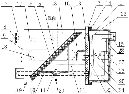
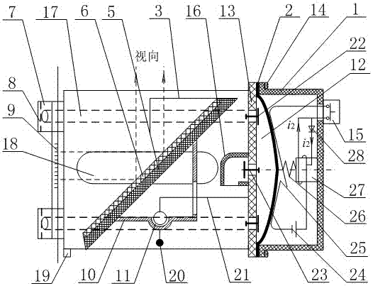
[0024] like figure 1 , as shown in 2, a measuring cylinder and measuring cup downward reading device, including a cover 1, a rubber magnetic film 2, an L-shaped overhanging vertical needle 3, a right groove wall 4-1, a left groove wall 4-2, a mirror frame 5, an embedded Mirror surface 6, hollow rubber suction cup 7, bracket grid 10, joint bearing 11, groove base 13, screw 14, normally open button 15, exhaust pipe air guide cover 16, air intake pipe 17, light transmission hole 18, foot 19, Metal gravity ball 20, cantilever 21, intake check valve 22, exhaust check valve 23, button battery 24, metal reed 25, spring 26, iron core coil 27, diode 28.

[0025] The rubber magnetic film 2 is composed of elastic soft magnetic rubber magnets. The rubber magnetic film 2 is sandwiched between the case 1 and the groove base 13. The three are connected and fixed with...


PUM


Abstract

The invention relates to a measuring cylinder and measuring glass overlook device. The hollow area of a hollow rubber suction cup is communicated with a groove base through an air inlet pipe in a right groove wall and an air inlet pipe in a left groove wall and penetrates through the groove base so as to be communicated with a vacuumizing device behind the groove base. A rubber magnetic thin film of the vacuumizing device is clamped between a shell and the groove base; an included angle of 45 degrees is formed between a mirror frame of an embedded mirror surface and the horizontal plane of a support grid, the embedded mirror surface is arranged in a scale mirror image device located between the right groove wall and the left groove wall, and a horizontal section of an L-shaped cantilever vertical needle is adhered to the center of the top of the mirror frame; the side surface of an outer ring of a joint bearing at the center of the plane of the support grid plane is fixedly welded to the support grid, a metal gravity ball with a rod is fixedly connected with the position under the outer ring, and an inner ring of the joint bearing is welded to an L-shaped cantilever of the groove base. During vacuumizing, the device is adsorbed to the side surface of a measuring cylinder or a measuring glass, when the L-shaped cantilever vertical needle is overlooked and only the horizontal section, overlapping with a mirror image, of the vertical needle is seen, vertical looking is achieved, mirror image values of scales can be read in an overlook mode, and side-looking reading is replaced.

Description

technical field [0001] The invention relates to a measuring cylinder and measuring cup, in particular to a measuring cylinder and measuring cup miniature overlooking reading device for experiments, which belongs to the technical field of measuring cylinder and measuring cup reading. Background technique [0002] Most of the measuring cylinders and measuring cups in current experiments require horizontal side-view readings. The reading process involves a series of actions such as turning the head, attaching the body, twisting the waist, etc., which is cumbersome and difficult to read accurately, especially for beginners, the side-view readings often have deviations. For this reason, patent announcement number CN103674155A discloses a kind of digital measuring cup, according to measuring cup bottom hydraulic pressure, combined with the liquid density of input, liquid volume is automatically displayed; method of reading. In view of the requirement that the density of the liqu...

Claims


Application Information

Patent Timeline
IPC IPC(8): G01F19/00
CPCG01F19/00
Inventor 孙逊
Owner SHANGHAI INSTITUTE OF TECHNOLOGY
Why Eureka
Try Eureka