Check patentability & draft patents in minutes with Patsnap Eureka AI!

Voltage control method for wind power plant reactive power control system

A voltage control method and power control technology, applied in wind power generation, reactive power compensation, reactive power adjustment/elimination/compensation, etc., can solve problems such as high voltage of 35kV bus, voltage increase, and wind farm voltage limit, etc. To achieve the effect of ensuring safe and stable operation

Active Publication Date: 2017-11-21
GUANGDONG MINGYANG WIND POWER IND GRP CO LTD
View PDF2 Cites 3 Cited by
  • Summary
  • Abstract
  • Description
  • Claims
  • Application Information

AI Technical Summary

Problems solved by technology

[0003] At present, the voltage control systems of wind farms only take the voltage at the grid-connected point, that is, the high-voltage side of the main transformer, as the control target, without considering that in extreme cases, if the reactive power command issued by the dispatcher does not match the voltage level of the wind farm, the Problems that cause wind farm voltage to exceed the limit
see image 3 Shown is the topological structure diagram of the wind farm. The output voltage of the wind turbines in the figure is generally 690V. Each wind turbine has a box-type transformer to raise the voltage to 35kV. Several box-type transformers are connected in parallel to the 35kV bus to form a line. The 35kV bus When installing reactive power compensation equipment, the high-voltage side of the wind farm grid-connected main transformer is generally selected as the control point by default, but in extreme cases, when the high-voltage side of the main transformer is used as the control target, it may cause the voltage limit of

Method used


Image

  • Voltage control method for wind power plant reactive power control system
  • Voltage control method for wind power plant reactive power control system
  • Voltage control method for wind power plant reactive power control system

Examples


Embodiment Construction

[0034] The present invention will be further described below in conjunction with specific examples.

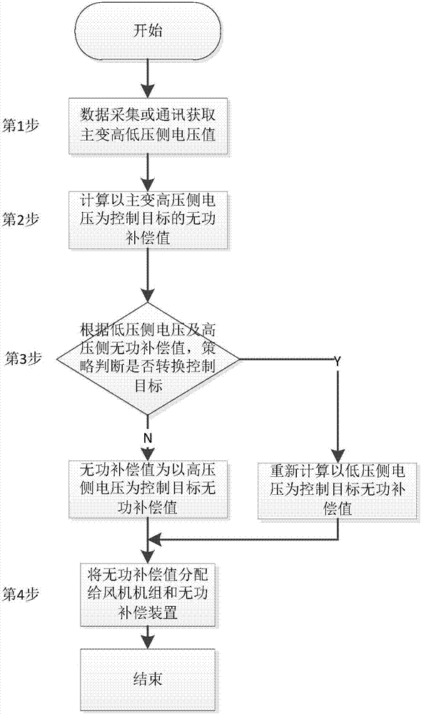
[0035] see figure 1 As shown, the voltage control method used in the wind farm reactive power control system provided by this embodiment is mainly to add the voltage cross-line target conversion function of the low-voltage side of the main transformer on the basis of taking the high-voltage side of the main transformer as the control point, so as to ensure The qualified range of the bus voltage on the 110kV side (high voltage side of the main transformer) of the wind farm and the stability of the bus voltage on the 35KV side (low voltage side of the main transformer) meet the dispatching requirements for regional reactive voltage control while taking into account the safe operation of the booster station The voltage level requirements; it specifically includes the following steps:

[0036] 1) Obtain the voltage effective value U of the high and low voltage sides of the main ...


PUM


Abstract

The invention discloses a voltage control method for a wind power plant reactive power control system. The method comprises the following steps: 1) acquiring data; 2) calculating a reactive power compensation value by taking stabilization of voltage at the high-voltage side of a main transformer as a control goal; 3), judging whether the control goal needs to be converted according to a voltage value at the lower-voltage side of the main transformer; and 4) distributing a calculated Q (n) value by the reactive power control system to a wind turbine set and a reactive power compensation device of a wind power plant so that the entire wind power plant can sufficiently realize a whole-plant reactive demand. According to the method provided by the invention, the target conversion function of the voltage across the low-voltage side of the main transformer is increased on the basis that the high-voltage side of the main transformer is taken as a control point so as to ensure the qualified range of bus voltage at a 110kV side (the high-voltage side of the main transformer) and the stability of bus voltage at a 35KV side (the low-voltage side of the main transformer), and while the control demand of dispatching for regional reactive voltage is satisfied, the voltage level requirements for safe operation of a booster station are taken into consideration.

Description

technical field [0001] The invention relates to the technical field of wind farm voltage control, in particular to a voltage control method for a wind farm reactive power control system. Background technique [0002] Wind power generation technology is becoming more and more mature, and has become an important new energy generation method. With the increasing proportion of wind power connected to the grid, the reactive power and voltage problems of wind farms are increasingly concerned and valued by wind power companies and grid companies. In the field of wind power generation technology, reactive power compensation and voltage control are important technical contents to ensure the healthy development of wind power. [0003] At present, the voltage control systems of wind farms only take the voltage at the grid-connected point, that is, the voltage on the high-voltage side of the main transformer, as the control target, without considering that in extreme cases, if the reac...

Claims


Application Information

Patent Timeline
IPC IPC(8): H02J3/18H02J3/38
CPCH02J3/1821H02J3/386Y02E10/76Y02E40/30
Inventor 朱敏唐彬伟
Owner GUANGDONG MINGYANG WIND POWER IND GRP CO LTD
Features
  • R&D
  • Intellectual Property
  • Life Sciences
  • Materials
  • Tech Scout
  • Unparalleled Data Quality
  • Higher Quality Content
  • 60% Fewer Hallucinations
Learn More