Signal transmitting and receiving methods and devices in communication system

A technology for signal transmission and communication systems, applied in transmission systems, multi-frequency code systems, digital transmission systems, etc.

Active Publication Date: 2017-11-21
BEIJING SAMSUNG TELECOM R&D CENT +1
View PDF8 Cites 11 Cited by
  • Summary
  • Abstract
  • Description
  • Claims
  • Application Information

AI Technical Summary

Problems solved by technology

[0006] This application provides a signal transmission and reception method and device in a communicati

Method used


Image

  • Signal transmitting and receiving methods and devices in communication system
  • Signal transmitting and receiving methods and devices in communication system
  • Signal transmitting and receiving methods and devices in communication system

Examples


Embodiment 1

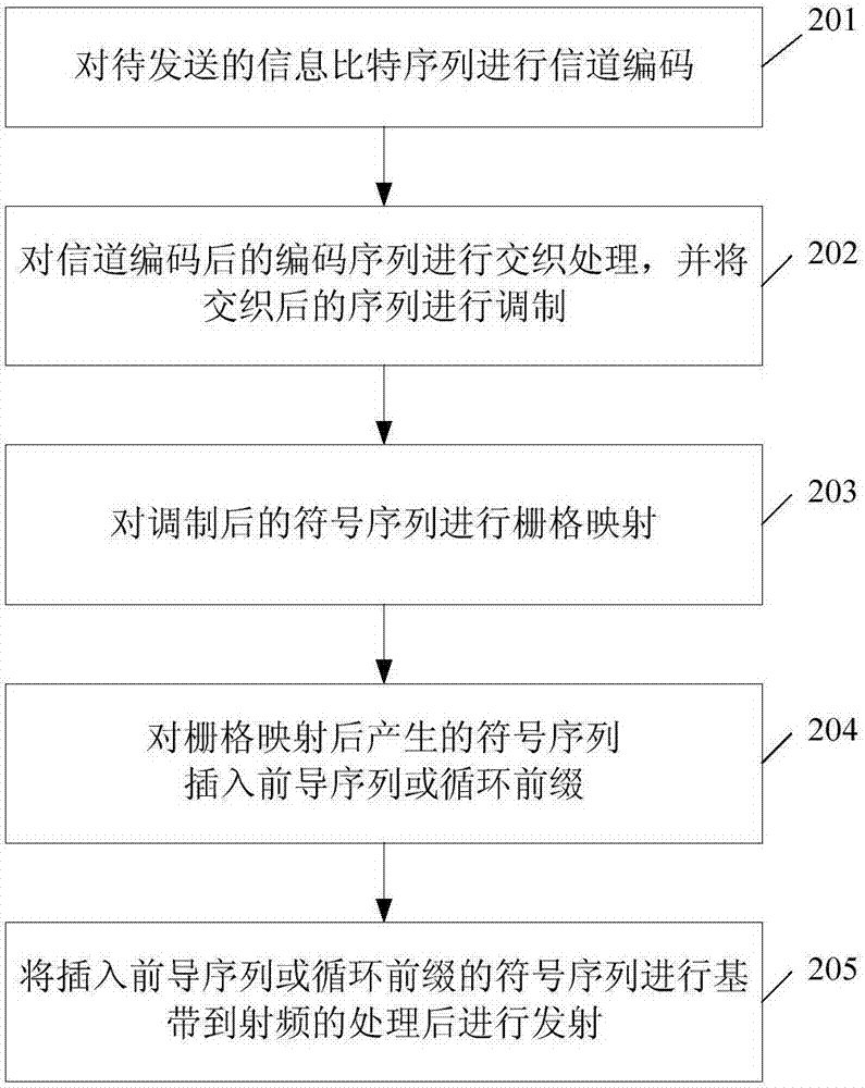
[0110] In this embodiment, we will introduce how the transmitter of the present invention works in combination with specific system configurations (such as channel coding parameters, interleaver and grid mapping design parameters, and allocation of preamble sequences).

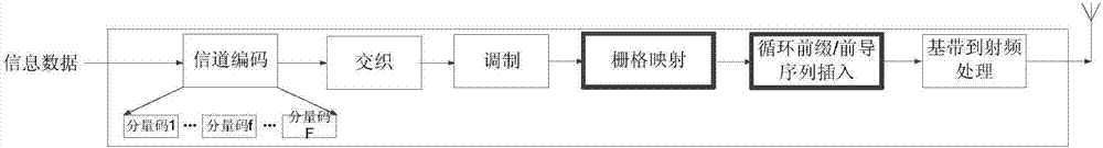
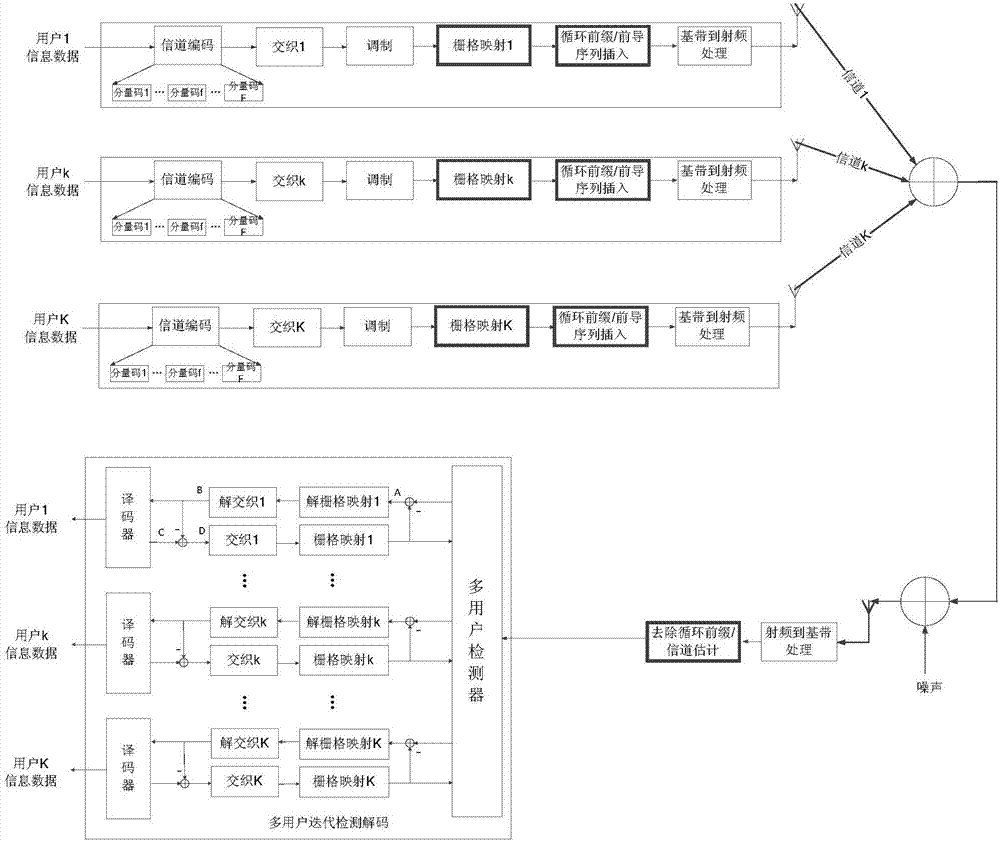
[0111] The schematic block diagram of the system is shown in image 3 shown. The transmitter obtains respective interleaving pattern information, grid mapping information and preamble configuration information from the physical broadcast channel, the physical downlink control channel or the physical downlink shared channel. The preamble configuration information indicates the preamble used by the user and the period of inserting the preamble. The interleaver and grid mapping information indicates an interleaving pattern and a grid mapping pattern, which may be indicated by means of a lookup table or the like. The system can directly configure the specific information of the interleaver, or let the transmitte...

Embodiment 2

[0117] In the first embodiment, a new transmitter and its multi-user iterative detection and decoding method are introduced. On this basis, this embodiment will introduce the multiple access method based on this transmitter.

[0118] The configuration of the transmitter and receiver of the system is as follows image 3 shown. The transmitter obtains respective interleaving pattern information, grid mapping information and preamble configuration information from the physical broadcast channel, the physical downlink control channel or the physical downlink shared channel. The preamble configuration information indicates the preamble used by the user and the period of inserting the preamble. The interleaver and grid mapping information indicates an interleaving pattern and a grid mapping pattern, which may be indicated by means of a lookup table or the like. The system can directly configure the specific information of the interleaver, or let the transmitter generate its own i...

Embodiment 3

[0140] In the first embodiment, it is introduced how the transmitter works in combination with specific system configurations (such as channel coding parameters, interleaver and grid mapping design parameters, and allocation of preamble sequences). As mentioned above, the insertion period of the preamble sequence can be predetermined, for example, stipulated by the protocol, or the insertion period of the preamble sequence can also be carried in the preamble sequence configuration information, where the insertion period can be determined by the system network side of. In this embodiment, the transmission method when the system decides that the transmitter sends the period of the preamble sequence will be introduced.

[0141] The schematic block diagram of the system is shown in image 3 shown. Consider a transmitter with an information bit sequence d of length M=126 k ={d k (m), m=0,...,M-1}, that is, the transmitter has 126 information bits. This information bit sequence...


PUM


Abstract

The application discloses a signal transmitting method in a communication system. The method comprises the steps of a, sequentially performing, by a transmitter, channel coding, modulation and grid mapping on an information bit sequence to be transmitted; and b, inserting a preamble sequence or a cyclic prefix into a symbol sequence generated after the grid mapping, performing baseband to radio frequency processing on the sequence inserted with the preamble sequence or the cyclic prefix, and then performing transmission, wherein the preamble sequence is periodically inserted and the cyclic prefix is inserted into the symbol sequence to which the preamble sequence is not inserted. With the application, the problem of high PAPR at the sending end is solved, and the efficiency of the PA is improved.

Description

technical field [0001] The present application relates to the technical field of wireless communication, and in particular to a signal transmitting method, a receiving method and a device thereof in a communication system. Background technique [0002] With the rapid development of the information industry, especially the growing demand from the mobile Internet and the Internet of Things (IoT, internet of things), unprecedented challenges are brought to future mobile communication technologies. For example, according to the report ITU-R M.[IMT.BEYOND 2020.TRAFFIC] of the International Telecommunication Union ITU, it can be predicted that by 2020, the growth of mobile traffic will increase by nearly 1,000 times compared to 2010 (4G era), and the number of user equipment connections will also increase. It will exceed 17 billion. As massive IoT devices gradually penetrate into mobile communication networks, the number of connected devices will become even more astonishing. In ...

Claims


Application Information

Patent Timeline
IPC IPC(8): H04L27/26
CPCH04L27/2615H04L1/0071H04L1/00H04L27/26H04L1/0041H04L1/0048H04L1/005H04J99/00
Inventor 钱辰熊琦喻斌付景兴郝辰曦
Owner BEIJING SAMSUNG TELECOM R&D CENT
Why Eureka
Try Eureka