Bonding device and bonding method

A laminating device and a laminating jig technology, which are applied in household appliances, other household appliances, household components, etc., can solve problems affecting product quality, low yield rate, and inability to fully discharge air bubbles, etc., to achieve good lamination effect, The effect of high yield

Active Publication Date: 2017-11-24
KUNSHAN GO VISIONOX OPTO ELECTRONICS CO LTD
View PDF3 Cites 47 Cited by
  • Summary
  • Abstract
  • Description
  • Claims
  • Application Information

AI Technical Summary

Problems solved by technology

[0003] The assembly process of the curved display device directly affects the performance of the display device. When bonding the flexible screen body and the cover plate of the display device, in order to fully discharge air bubbles during lamination, especially the air bubbles in the R corner area at the edge of the cover plate , usually using a jig with the same size and shape as the cover plate for l

Method used


Image

  • Bonding device and bonding method
  • Bonding device and bonding method
  • Bonding device and bonding method

Examples


no. 1 example

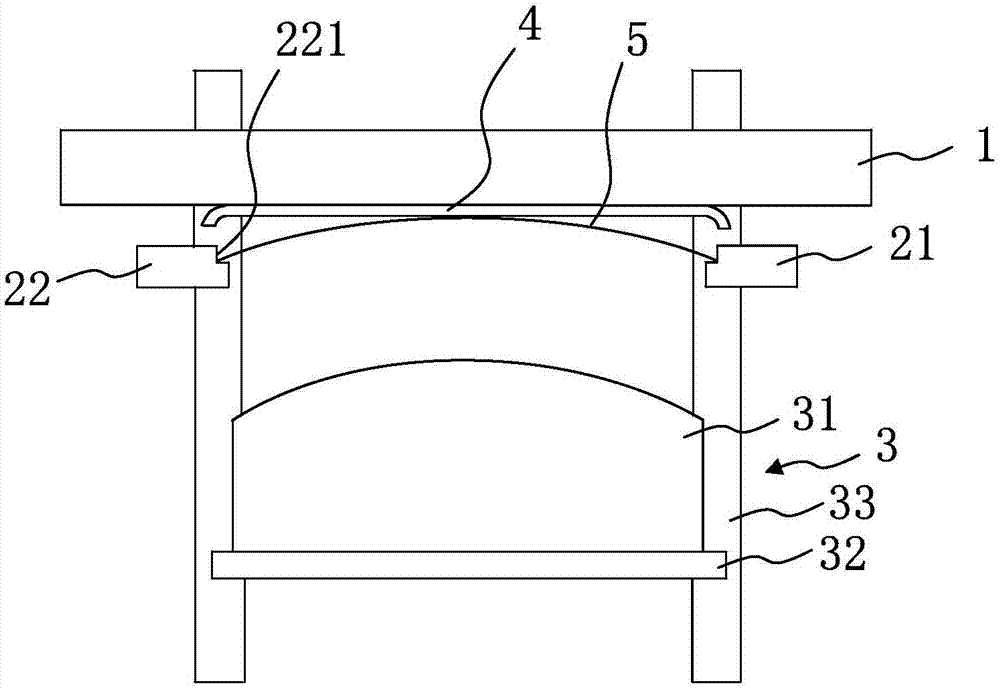
[0030] figure 1 It is a schematic structural diagram of the bonding device in the first embodiment of the present invention. Such as figure 1 As shown, the laminating device of this embodiment includes a cover plate positioning mechanism 1 , a flexible screen body positioning mechanism and a laminating jig 3 .

[0031] The cover plate positioning mechanism 1 is used for fixing the cover plate 4 . Specifically, the cover positioning mechanism 1 can fix the cover 4 by means of vacuum adsorption, so that the cover 4 can be positioned toward the flexible screen body positioning mechanism. In this embodiment, the edge regions of the long sides on both sides of the cover plate 4 are curved surfaces, that is, the long sides on both sides of the cover plate 4 are provided with R angles. It can be understood that, according to the shape design of the cover plate 4 , the edge regions of the short sides on both sides of the cover plate 4 may also be curved surfaces, that is, the short...

no. 2 example

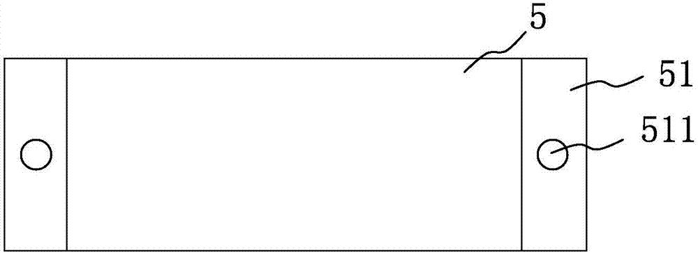
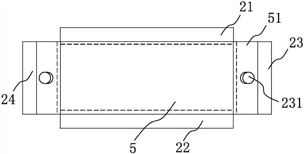
[0039] figure 2 It is a schematic structural diagram of the flexible screen body in the second embodiment of the present invention. image 3 It is a schematic diagram of the positioning method of the flexible screen in the second embodiment of the present invention. Figure 4 It is a schematic structural diagram of the bonding device in the second embodiment of the present invention. In addition, for the structural diagram of the laminating device in this embodiment in another direction, please refer to figure 1 . Such as Figure 1 to Figure 4 As shown, the main difference between the laminating device of this embodiment and the first embodiment is that the flexible screen body positioning mechanism also includes a third positioning seat 23 located between the first positioning seat 21 and the second positioning seat 22 and opposite to each other. with the fourth positioning seat 24, wherein, image 3 It is only for illustration, and is not used to define the distance re...

no. 3 example

[0046] Figure 5 It is a schematic flow chart of the bonding method in the third embodiment of the present invention. Such as Figure 5 Shown, bonding method of the present invention may comprise the following steps:

[0047]Step 61, fixing the cover plate on the cover plate positioning mechanism.

[0048] Specifically, the cover positioning mechanism 1 can fix the cover 4 by means of vacuum adsorption, so that the cover 4 can be positioned toward the flexible screen body positioning mechanism. In this embodiment, the edge regions of the long sides on both sides of the cover plate 4 are curved surfaces, that is, the long sides on both sides of the cover plate 4 are provided with R angles. It can be understood that, according to the shape design of the cover plate 4 , the edge regions of the short sides on both sides of the cover plate 4 may also be curved surfaces, that is, the short sides on both sides of the cover plate 4 are provided with R angles. Certainly, the cover ...


PUM

PropertyMeasurementUnit
Shore hardnessaaaaaaaaaa

Abstract

The invention discloses a bonding device. The bonding device comprises a cover plate positioning mechanism, a flexible screen body positioning mechanism and a bonding tool; the cover plate positioning mechanism is used for fixing a cover plate; the bonding tool comprises a deformable pressure head capable of pushing to the cover plate positioning mechanism; the flexible screen body positioning mechanism is positioned between the cover plate positioning mechanism and the deformable pressure head; the flexible screen body positioning mechanism is used for fixing a flexible screen body and pushing the flexible screen body before bonding, so that the flexible screen body is changed from a plane state to a curve state of the middle area in contact positioning with the cover plate; the front end of the deformable pressure head is curved, and the highest curve place of the front end is corresponding to the position of the middle area of the flexible screen body; and the front end of the deformable pressure head is pressed by the cover plate to deform according to the shape of the cover plate. The invention further provides a bonding method. The bonding device and method can fully discharge bubbles from the middle area to the edge of the flexible screen body during bonding to adapt to cover plates with different shapes so as to achieve good bonding effect and high yield.

Description

technical field [0001] The invention relates to the field of display technology, in particular to a laminating device and a laminating method. Background technique [0002] With the development of display devices, curved display devices using flexible screens are becoming more and more popular. The flexible screen has the advantages of being lighter and thinner in size, low power consumption, and improving the battery life of the device. At the same time, based on its bendable and flexible characteristics, its durability is also much higher than that of traditional screens, which can reduce equipment accidents. probability of injury. [0003] The assembly process of the curved display device directly affects the performance of the display device. When bonding the flexible screen body and the cover plate of the display device, in order to fully discharge air bubbles during lamination, especially the air bubbles in the R corner area at the edge of the cover plate , usually u...

Claims


Application Information

Patent Timeline
IPC IPC(8): B29C65/56B29C65/78B29L31/34
Inventor 熊佩林
Owner KUNSHAN GO VISIONOX OPTO ELECTRONICS CO LTD
Why Eureka
Try Eureka