Auxiliary facility for new energy vehicle

A technology for new energy vehicles and facilities, applied in electric vehicles, electric vehicle charging technology, vehicle energy storage, etc., can solve the problems of affecting charging use, falling off of charging terminals, single setting mode, etc., to achieve high charging stability, prevent The effect of charging interruption and high charging safety

Active Publication Date: 2017-11-24
WM MOTOR TECH GRP CO LTD
View PDF5 Cites 4 Cited by
  • Summary
  • Abstract
  • Description
  • Claims
  • Application Information

AI Technical Summary

Problems solved by technology

Charging piles are supporting facilities for new energy vehicles and are carriers for charging new energy vehicles. However, the traditional charging piles have a single setting mode, and the charging process only depends on the friction force when the charging terminal and the charging port are plugged in to maintain a stationary state. If you accidentally touch the charging terminal or be affected by the pulling of the charging cable, the charging terminal may fall off from the charging port, causing charging interruption, which seriously affects the normal charging use. At the same time, the traditional charging port The conductive sheet is generally set relatively outside. This conductive sheet is easily touched by the metal sheet or metal rod. Therefore, when a person who lacks safety awareness inserts the metal sheet or metal rod into the charging port, an electric shock accident is likely to occur. It is easy to cause casualties and there is a big safety hazard

Method used


Image

  • Auxiliary facility for new energy vehicle
  • Auxiliary facility for new energy vehicle
  • Auxiliary facility for new energy vehicle

Examples


Embodiment Construction

[0023] All features disclosed in this specification, or steps in all methods or processes disclosed, may be combined in any manner, except for mutually exclusive features and / or steps.

[0024] Any feature disclosed in this specification (including any appended claims, abstract and drawings), unless expressly stated otherwise, may be replaced by alternative features which are equivalent or serve a similar purpose. That is, unless expressly stated otherwise, each feature is one example only of a series of equivalent or similar features.

[0025] Combine below Figure 1-5 The present invention will be described in detail.

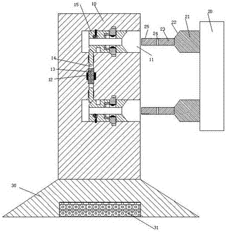
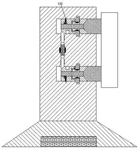
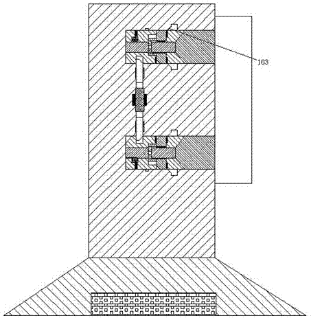
[0026] refer to Figure 1-5, according to an embodiment of the present invention, a new energy vehicle supporting facility includes a charging pile 10 and a charging terminal 20 connected to the new energy vehicle, and the charging pile 10 is provided with a chute 11 with its mouth facing right up and down. , a sliding seat 15 is smoothly installed in the ...


PUM


Abstract

The invention discloses an auxiliary facility for a new energy vehicle. The auxiliary facility for the new energy vehicle includes a charging pile and a charging tip which is connected with the new energy vehicle, wherein slide grooves with rightward ports are formed in the charging pile vertically and correspondingly, and a slide base is smoothly installed in each slide groove; a through groove is formed between the two slide grooves, and an iron prop is fixedly arranged on the midpoint of the through groove; a coil is fixedly arranged on the outside of the iron prop, and sliding arms are arranged in the through groove vertically, correspondingly and smoothly; jacks which are communicated from left to right are formed in midpoints of the slide bases, and the right end surface of each slide base is provided with a guide sliding surface connected with the jacks; first pushing grooves communicated with the jacks are formed in the slide bases vertically and correspondingly, and first pushing blocks are smoothly arranged in the first pushing grooves; contact pieces are fixedly arranged on the end surfaces, toward the jacks, of the first pushing blocks, and first concave holes matched with the first pushing blocks are formed in end walls of the slide grooves vertically and correspondingly; left ends of the first pushing grooves are provided with connecting holes communicated with the first pushing grooves and the jacks.

Description

technical field [0001] The invention relates to the field of new energy vehicles, in particular to a new energy vehicle supporting facility. Background technique [0002] New energy vehicles are gradually replacing traditional vehicles with many advantages such as energy saving, environmental protection and pollution-free, and are widely used. Charging piles are supporting facilities for new energy vehicles and are carriers for charging new energy vehicles. However, the traditional charging piles have a single setting mode, and the charging process only depends on the friction force when the charging terminal and the charging port are plugged in to maintain a stationary state. If you accidentally touch the charging terminal or be affected by the pulling of the charging cable, the charging terminal may fall off from the charging port, causing charging interruption, which seriously affects the normal charging use. At the same time, the traditional charging port The conductive...

Claims


Application Information

Patent Timeline
Patent Type & Authority Applications(China)
IPC IPC(8): B60L11/18
CPCB60L53/16B60L53/31Y02T10/70Y02T10/7072Y02T90/12Y02T90/14
Inventor 陈淑尧
Owner WM MOTOR TECH GRP CO LTD
Why Eureka
Try Eureka