Aircraft equipped with fire-fighting unit and rescuing facility

A technology for a fire-fighting device and an aircraft, applied in the field of aircraft, can solve problems such as the inability to rescue high-rise buildings, the difficulty of fire trucks, and the inability of high-rise personnel to be rescued.

Active Publication Date: 2017-11-24
盐城项果科技有限公司
View PDF5 Cites 3 Cited by
  • Summary
  • Abstract
  • Description
  • Claims
  • Application Information

AI Technical Summary

Problems solved by technology

The 101-meter aerial ladder vehicle is currently the tallest fire-fighting aerial ladder vehicle in China, with a height of about 35 floors; with the changes in the city, there are more and more tall buildings and narrower streets, but when a fire or other disaster occurs in a high-rise building When the fire engine is in trouble, it is difficult to reach the corresponding rescue point in time, and even if it arrives, it will not be able to rescue the disaster in the high-rise building, and the high-rise personnel cannot be rescued. Firefighting equipment for first aid and rescue of persons

Method used


Image

  • Aircraft equipped with fire-fighting unit and rescuing facility
  • Aircraft equipped with fire-fighting unit and rescuing facility
  • Aircraft equipped with fire-fighting unit and rescuing facility

Examples


Embodiment 2

[0026] Embodiment 2, compared with Embodiment 1; in order to make the combination of the two more stable when the slider 3 slides to a suitable position on the chute, a plurality of reinforcement holes are provided on the front side walls of the front and rear beams, and the slider 3 is provided with a boss matching the reinforcement hole, and the slide 3 is provided with an electro-hydraulic device and a bearing plate. One side of the bearing plate is fixed, and the other side of the bearing plate is fixed with one end of the boss; furthermore, the electrohydraulic device is an electrohydraulic rod.

Embodiment 3

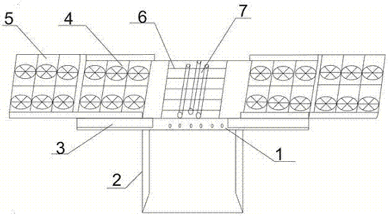
[0027] Embodiment 3, compared with Embodiment 2, the bottom of the front and rear beams of the fire stand 2 is provided with a rack, the sliding part 3 is a Z-shaped cavity, and the lower cavity of the sliding part 3 is provided with a driving power source and a gear. The output end of the source is fixedly connected with the gear, and the gear is meshed with the rack; the upper cavity of the sliding frame is combined with the upper cavity corresponding to another sliding frame to form the third flying wing device 5 or the fourth flying wing device; for example: drive The power source drives the gear to move on the rack, and indirectly makes the slider 3 move on the front beam body; the driving power source is a motor.

[0028] Furthermore, in order to make the sliding part 3 safer when moving on the fire stand 2, a slide rail is provided on the top of the front and rear beams of the fire stand 2, and the top of the lower cavity of the slide part 3 is provided with a slide rail...


PUM


Abstract

The invention discloses an aircraft equipped with a fire-fighting unit and a rescuing facility. The aircraft is provided with a flying-wing fixing frame and a fire-fighting rack, wherein the flying-wing fixing frame is provided with, from left to right, a left placement area, a middle placement area and a right placement area; the fire-fighting rack is arranged in the middle placement area; a first flight wing device and a second flight wing device are respectively arranged in the left placement area and the right placement area; the upper parts of the left placement area and the right placement area are respectively provided with a third flight wing device and a fourth flight wing device; the third flight wing device and the fourth flight wing device are both slidably connected with the flying-wing fixing frame; the fire-fighting rack is internally provided with a first fire-fighting workbench, a rescue capsule and a second fire-fighting workbench; the first fire-fighting workbench is provided with a fire-fighting equipment placing rack and a firefighter workbench; the rescue capsule is composed of a multi-section capsule body unit and an expansion device; the output terminal of the expansion device is fixedly connected with the multi-section capsule body unit; a connecting device is arranged in the capsule body unit and used for butt joint of the rescue capsule with a rescue building.

Description

technical field [0001] The invention belongs to the field of fire-fighting equipment, and in particular relates to an aircraft with a fire-fighting device and rescue facilities. Background technique [0002] At present, the highest fire ladder in the world can be raised to 112 meters, about 40 floors high. The 101-meter aerial ladder vehicle is currently the tallest fire-fighting aerial ladder vehicle in China, with a height of about 35 floors; with the changes in the city, there are more and more tall buildings and narrower streets, but when a fire or other disaster occurs in a high-rise building When the fire engine is in trouble, it is difficult to reach the corresponding rescue point in time, and even if it arrives, it will not be able to rescue the disaster in the high-rise building, and the high-rise personnel cannot be rescued. Firefighting equipment for rescue and rescue of persons. Contents of the invention [0003] The present invention provides an aircraft wit...

Claims


Application Information

Patent Timeline
Patent Type & Authority Applications(China)
IPC IPC(8): B64C1/30B64C27/04B64D1/16A62C3/02
CPCA62C3/0214B64C1/30B64C27/04B64D1/16
Inventor 程克
Owner 盐城项果科技有限公司
Why Eureka
Try Eureka