Supercharge Your Innovation With Domain-Expert AI Agents!

Efficient installation structure of switch socket panel and bottom case

A socket panel and installation structure technology, applied in the direction of coupling device, connecting device parts, electrical components, etc., can solve the problems of difficult installation, difficult installation, low work efficiency, etc., to solve the problem of low installation efficiency and improve The effect of working efficiency and reducing labor intensity

Pending Publication Date: 2017-11-24
中山市中法维能电气有限公司
View PDF11 Cites 0 Cited by
  • Summary
  • Abstract
  • Description
  • Claims
  • Application Information

AI Technical Summary

Problems solved by technology

[0002] The panel of the traditional switch socket is installed on the bottom box by screws. Since the bottom box is pre-mounted on the wall, the installer cannot see the corresponding threaded hole when installing the panel, which makes the installation difficult and inefficient. For this reason, the publication number is The patent document "CN202042695U" discloses "a switch socket bottom box". It solves the problem of the alignment between the screw and the screw hole, reduces the difficulty of installation, and improves the installation efficiency. However, due to the length of the screw, a small swing at the rear end of the screw will cause a large swing at the front end. It is hard and has a certain degree of elasticity. It is necessary to press the panel with one hand and install the screws with the other hand. The installation is still difficult and the work efficiency is still not high. The defect that this type of product is difficult to install has not been fundamentally solved.

Method used


Image

  • Efficient installation structure of switch socket panel and bottom case
  • Efficient installation structure of switch socket panel and bottom case
  • Efficient installation structure of switch socket panel and bottom case

Examples


Embodiment Construction

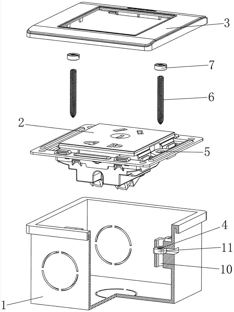
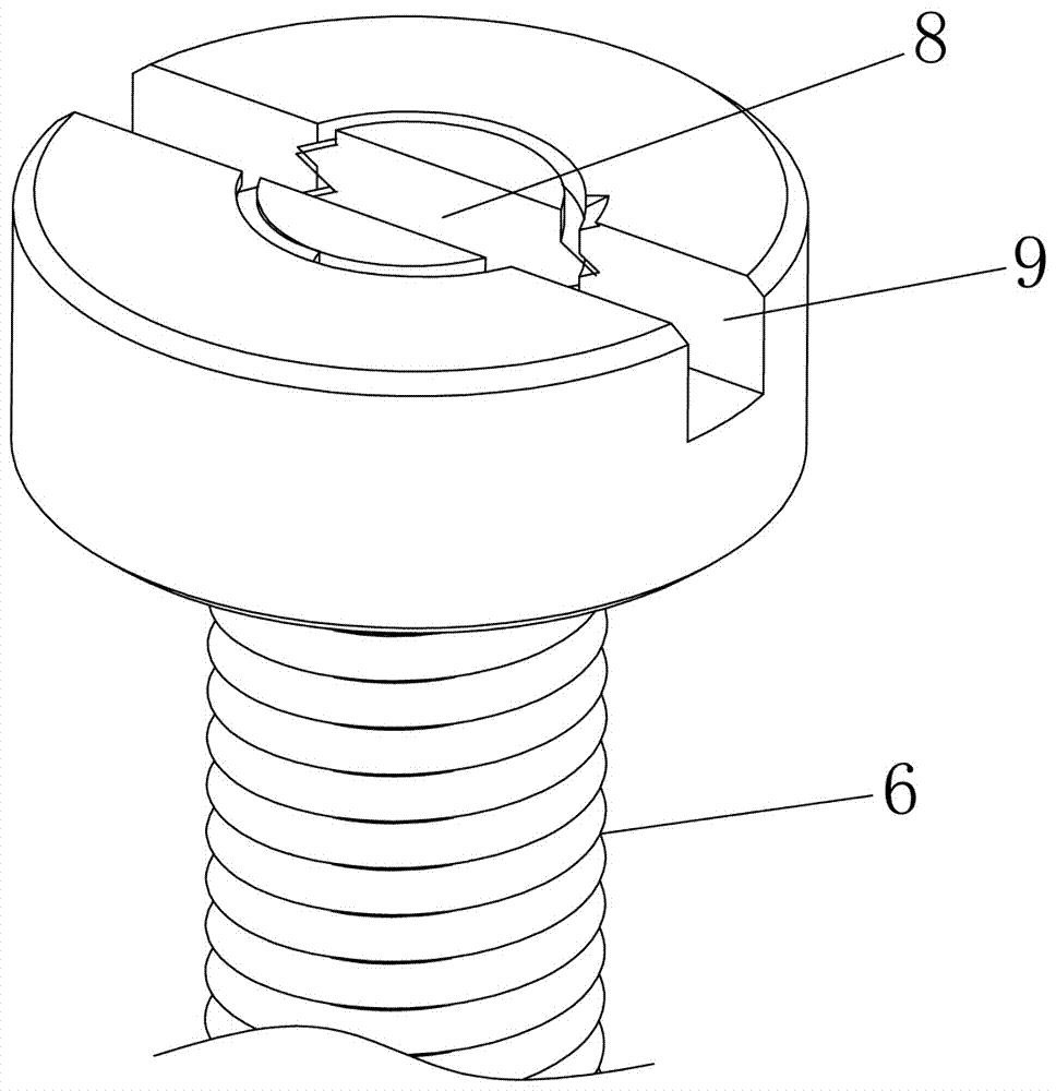
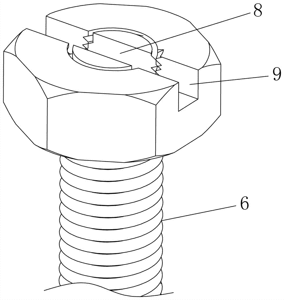
[0012] refer to Figure 1 to Figure 3 , an efficient installation structure for a switch socket panel and a bottom box, comprising a bottom box 1, a panel 2, a screw 6 and a face frame 3, the face frame 3 is fastened on the face plate 2, and the fastening of the face plate 2 and the face frame 3 The structure is the same as the fastening structure between the socket or the switch panel and the bottom box in the prior art. The bottom box 1 is provided with a screw hole 4, and the panel 2 is provided with a fixing hole 5, and the front end of the screw rod 6 is threadedly connected in the screw hole 4, and the panel 2 is packed into the bottom box 1 to make the screw rod 6 After the rear end passes through the fixing hole 5, a locking nut 7 is threadedly installed on the rear end of the screw rod 6, and a linkage structure is arranged on the locking nut 7 and the screw rod 6.

[0013] If the linkage structure is not provided, the exposed part of the screw rod 6 is too long and ...


PUM


Abstract

The invention discloses an efficient installation structure of a switch socket panel and a bottom case. The efficient installation structure comprises the bottom case, the panel and screws, wherein screw holes are formed in the bottom base, fixing holes are formed in the panel, front end threads of the screws are connected in the screw holes, rear-end threads are provided with locking nuts, and a linkage structure formed by a nut groove and a screw groove is arranged on each locking nut and the corresponding screw. During installation, the screws are installed in the screw holes of the bottom case, the panel is arranged in the bottom case, the rear ends of the screws pass through the fixing holes of the panel, the locking nuts are installed on the screws and are rotated, the locking nuts and the screws are rotated together by using a tool when the end surfaces of the locking nuts and the screws are level and the nut grooves and the screw grooves are aligned, the panel is fixed on the bottom case, and finally a surface frame is buckled on the panel. According to the surface frame, the alignment of the screws and the fixing holes can be seen, the installation is convenient and fast, the working efficiency is effectively improved, the labor intensity is greatly reduced, and the problem of low installation efficiency of the switch socket is solved completely.

Description

technical field [0001] The present invention relates to a basic electrical component, especially a switch or socket. Background technique [0002] The panel of the traditional switch socket is installed on the bottom box by screws. Since the bottom box is pre-mounted on the wall, the installer cannot see the corresponding threaded hole when installing the panel, which makes the installation difficult and inefficient. For this reason, the publication number is The patent document "CN202042695U" discloses "a switch socket bottom box". It solves the problem of the alignment between the screw and the screw hole, reduces the difficulty of installation, and improves the installation efficiency. However, due to the length of the screw, a small swing at the rear end of the screw will cause a large swing at the front end. It is hard and has a certain degree of elasticity. It is necessary to press the panel with one hand and install the screws with the other hand. The difficulty of i...

Claims


Application Information

Patent Timeline
IPC IPC(8): H01R13/506
CPCH01R13/506
Inventor 杨文雄
Owner 中山市中法维能电气有限公司
Features
  • R&D
  • Intellectual Property
  • Life Sciences
  • Materials
  • Tech Scout
  • Unparalleled Data Quality
  • Higher Quality Content
  • 60% Fewer Hallucinations
Learn More