Blood pressure measurement device
A sphygmomanometer and user technology, applied in blood vessel assessment, diagnostic recording/measurement, sensors, etc., can solve problems such as user burden, and achieve the effect of simple blood pressure
- Summary
- Abstract
- Description
- Claims
- Application Information
AI Technical Summary
Problems solved by technology
Method used
Image
Examples
Embodiment approach 1
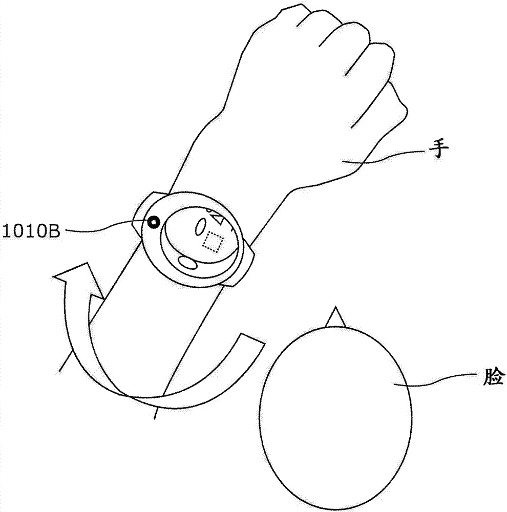
[0101] The wrist-watch type blood pressure measurement device 100 according to Embodiment 1 will be described. image 3 An example of use of the watch-type blood pressure measurement device 100 in Embodiment 1 is shown. Such as image 3 As shown, the blood pressure measurement device 100 captures an image of at least a part of the user's face while being worn on the user's wrist, and uses the image of at least a part of the face to measure the user's blood pressure.
[0102] [structure of blood pressure measurement device]
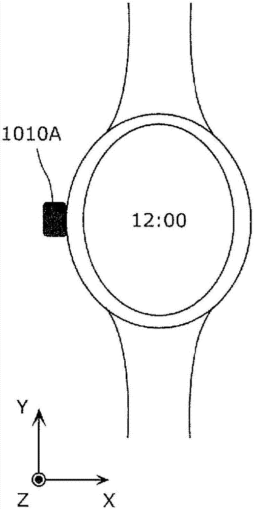
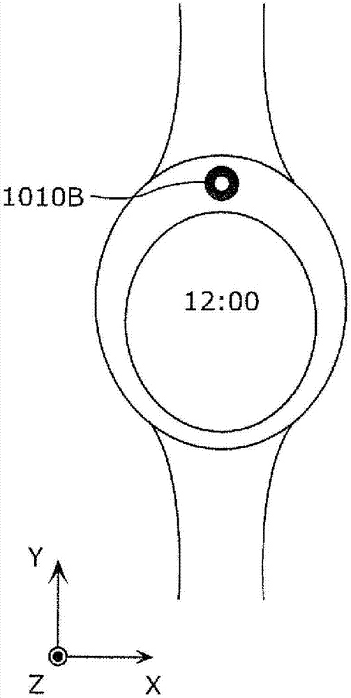
[0103] Here, refer to Figure 4A ~ Figure 4C , the structure of the blood pressure measurement device 100 of this embodiment will be described. Figure 4A It is a plan view of the blood pressure measurement device 100 according to the first embodiment. That is, Figure 4A The outer surface of the blood pressure measurement device 100 is shown. Figure 4B It is a bottom view of blood pressure measurement device 100 according to Embodiment 1. That is, ...
Embodiment approach 2
[0198] In Embodiment 2, when the amount of light irradiated on the user's face is insufficient, an instruction to move the position of the blood pressure measurement device is displayed based on the brightness of the image captured by the imaging unit.
[0199] In addition, the structure and functional configuration of the blood pressure measurement device according to the present embodiment are the same as or similar to those of the blood pressure measurement device according to Embodiment 1, and therefore illustration and description thereof will be appropriately omitted.
[0200] Figure 18 It is a diagram showing an example of an instruction given to the user by the blood pressure measurement device 200 according to the second embodiment.
[0201] The user is irradiated with light from the lighting fixture when indoors and light from the sun when outdoors. So basically, the light source is positioned above the user. When the user uses the blood pressure measurement devic...
Embodiment approach 3
[0210] In addition, as in Embodiment 2, if the wrist is raised to ensure the amount of light irradiated to the face, the pulse wave propagation time will change due to the influence of gravity, etc., so the estimation accuracy of blood pressure may decrease. . Therefore, in Embodiment 3, the content of the instruction for backlighting is changed according to the position (height) of the wrist.
[0211] In addition, the structure and functional configuration of the blood pressure measurement device according to the present embodiment are the same as or similar to those of the blood pressure measurement device according to Embodiment 1, and therefore illustration and description thereof will be appropriately omitted.
[0212] Figure 20 as well as Figure 21 It is a diagram showing an example of an instruction given to the user by the blood pressure measurement device 300 according to the third embodiment. Such as Figure 20 In that way, a threshold height (for example, 30 d...
PUM
 Abstract
Description
Claims
Application Information
 - R&D
- Intellectual Property
- Life Sciences
- Materials
- Tech Scout
- Unparalleled Data Quality
- Higher Quality Content
- 60% Fewer Hallucinations
Browse by: Latest US Patents, China's latest patents, Technical Efficacy Thesaurus, Application Domain, Technology Topic, Popular Technical Reports.
© 2025 PatSnap. All rights reserved.Legal|Privacy policy|Modern Slavery Act Transparency Statement|Sitemap|About US| Contact US: help@patsnap.com


