Automatic closing structure for sliding cover

An automatic closing and sliding cover technology, applied in building construction, building locks, buildings, etc., can solve the problems of stuck position, safety accident, fingers caught in the gap, etc.

Inactive Publication Date: 2017-11-28
WENZHOU JUSHI SECURITY TECH CO LTD
View PDF5 Cites 2 Cited by
  • Summary
  • Abstract
  • Description
  • Claims
  • Application Information

AI Technical Summary

Problems solved by technology

[0004] Now most of the products of manufacturers will install a sliding cover on the front electronic door lock. When using fingerprints, you have to pull it up and down. Pull down to cover the fingerprint head. During the movement of the sliding cover, it will be in a free fall state, and the user's fingers may be caught in the gap or hit by the lower edge of the sliding cover, causing safety accidents.
When the sliding cover falls freely or is pulled down by hand, the collision will also produce noise after sliding down to the right position. At the same time, the sliding cover will collide with the main body of the door lock, which will also cause damage to both and reduce the service life.

Method used


Image

  • Automatic closing structure for sliding cover
  • Automatic closing structure for sliding cover
  • Automatic closing structure for sliding cover

Examples


Embodiment Construction

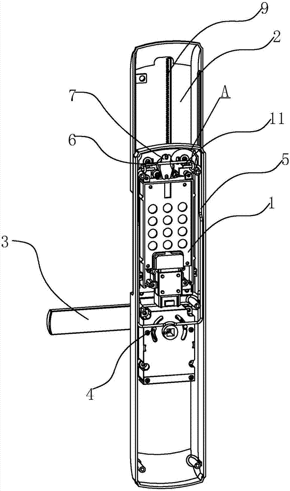
[0016] Refer to attached Figure 1 to Figure 4 A sliding cover automatic closing structure of the present invention will be further described in detail.

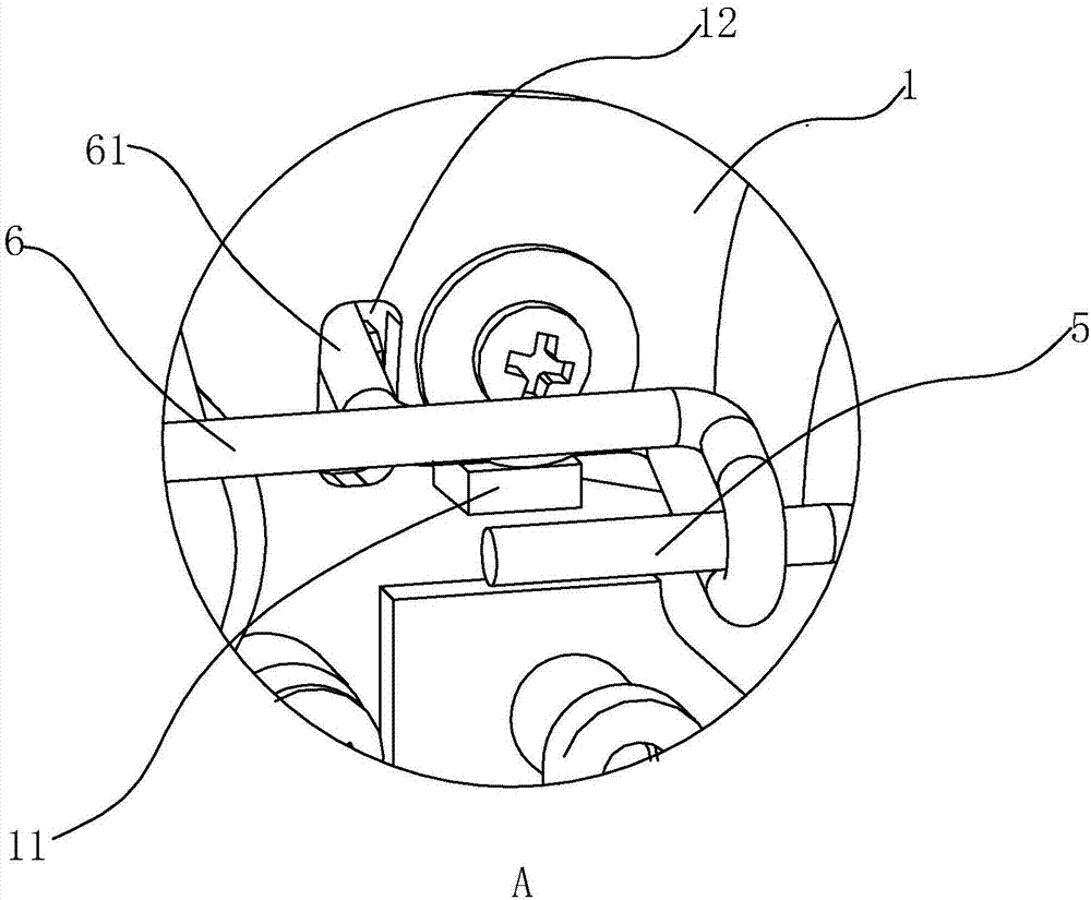
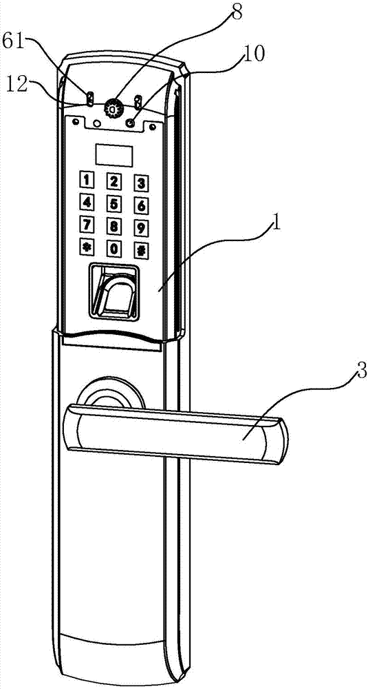
[0017] A sliding cover automatic closing structure, comprising a door lock main body 1, a sliding cover 2 and a handle 3; one end of the handle 3 is rotatably arranged on the door lock main body 1, and the end is provided with a rotating column 4, A push rod 5 is arranged above the rotating column 4; one end of the pushing rod 5 abuts on the rotating column 4, and the other end is linked with a shift fork 6, and the door lock main body 1 is provided with a shift fork. 6, the swing fulcrum 11, the shift fork 6 is provided with a hook 61, and the push rod 5 moves upward to push the hook 61 of the shift fork 6 to swing downward around the swing fulcrum 11;

[0018] The door lock main body 1 is provided with a toggle chute 12, and the hook 61 passes through the toggle chute 12 to be connected with the slide cover 2; the door lo...


PUM


Abstract

The invention discloses an automatic closing structure for a sliding cover. The automatic closing structure comprises a door lock body, the sliding cover and a lever handle, wherein one end part of the lever handle is rotationally arranged on the door lock body, a rotating column is arranged at the end part, and a push rod is arranged above the rotating column; one end part of the push rod is butted against the rotating column, and the other end of the push rod is linked with a shifting fork; the shifting fork is provided with a hook part; a stirring sliding chute is formed in the door lock body, and the hook penetrates through the stirring sliding chute to be connected with the sliding cover; a positioning concave part is formed in the inner side face of the sliding cover, a positioning piece matched with the positioning concave part is arranged on the door lock body and is used for positioning the opened sliding cover. When the lever handle is rotated to unlock a door lock, the rotating column can drive the push rod to move up, the hook part of the shifting fork is driven to swing downwards to push the sliding cover to slide down, and thus the sliding cover is automatically closed. In the moving-down process of the sliding cover, a rack and a gear relatively move, a damper enables the sliding cover to slowly drop down through the engagement of the gear and the rack, and the sliding cover and the door lock body cannot collide with each other to make a sound.

Description

technical field [0001] The invention relates to the technical field of electronic door locks, more specifically, it relates to an automatic closing structure of a sliding cover. Background technique [0002] In the prior art, locks are mainly divided into traditional mechanical locks and electronic locks developed later. Although mechanical locks are simple in structure, they have few passwords and poor security performance; electronic locks are safe because of their large passwords. Therefore, it has been widely used in various fields. [0003] In order to protect the various functional devices of the electronic door lock (such as sensing devices or password input devices, etc.), a slide cover is usually provided outside the main body of the electronic door lock, and the various exposed functional devices are covered by the slide cover, so that play a protective role. [0004] Now most of the products of manufacturers will install a sliding cover on the front electronic d...

Claims


Application Information

Patent Timeline
Patent Type & Authority Applications(China)
IPC IPC(8): E05B17/00
CPCE05B17/00E05B17/0045
Inventor 陈锰
Owner WENZHOU JUSHI SECURITY TECH CO LTD
Why Eureka
Try Eureka