In addition, since it is necessary to change the DC power supply circuit in this way, there is also a problem that development man-hours increase
Method used
Image
Click on the blue label to locate the original text in one second.
Reading with bidirectional positioning of images and text.
Examples
Embodiment 1
[0034] [structure of the lighting equipment]
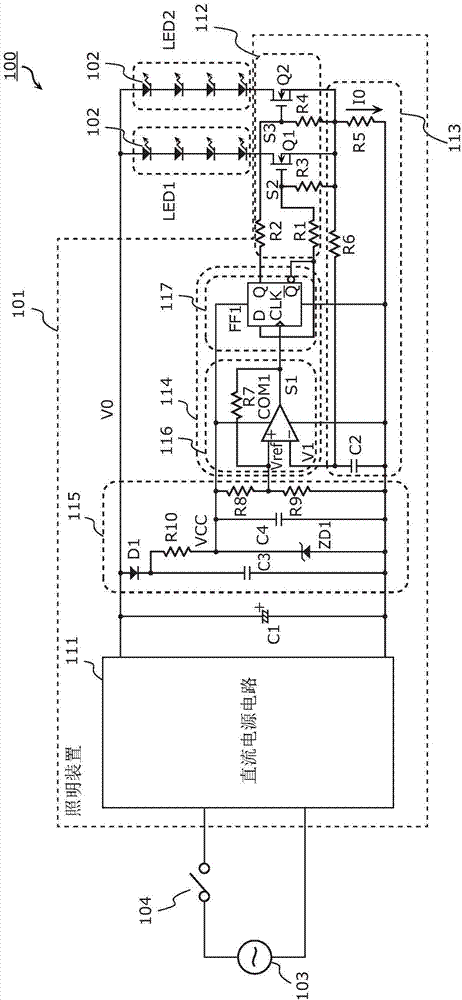
[0035] First, the configuration of the lighting fixture 100 according to the present embodiment will be described. figure 1 It is a figure which shows the structure of the lighting fixture 100 which concerns on this Example. Such as figure 1 As shown, the lighting fixture 100 includes a lighting device 101 and a plurality of light emitting elements 102 .
[0036] The lighting device 101 turns on a plurality of light emitting elements 102 using electric power from a commercial power supply 103 . Furthermore, a power switch 104 such as a wall switch is connected between the lighting device 101 and the commercial power supply 103 . That is, when the power switch 104 is turned on and off, the power supply from the commercial power supply 103 to the lighting device 101 is switched on and off, and the power supply to the light emitting element 102 is switched on and off.
[0037] The lighting device 101 includes a DC power supply ci...
Deformed example 1
[0063] Figure 5 It is a figure which shows the structural example of 100 A of lighting fixtures concerning the modification 1 of this Example. exist Figure 5 In the illustrated lighting fixture 100A, the number of series-connected light-emitting elements 102 included in the light-emitting group LED1 (number of light-emitting elements 102 connected in series) is greater than the number of series-connected light-emitting elements 102 included in the light-emitting group LED2. Furthermore, the switching circuit 112A includes only the switching element Q2 connected in series to the light emission group LED2. That is, the light emitting group LED1 is not connected in series with the switching element.
[0064] In this case, while the switching element Q2 is on, current flows only in the light-emitting group LED2 having a small number of series connections, ie, a low forward voltage, among the light-emitting groups LED1 and LED2 . On the other hand, while the switching element ...
Deformed example 2
[0068] Figure 6 It is a figure which shows the structural example of the lighting fixture 100B which concerns on the modification 2 of this Example. exist Figure 6 In the illustrated lighting fixture 100B, the light emitting group LED1 and the light emitting group LED2 are connected in series. Furthermore, the switching circuit 112B includes only the switching element Q2 connected in parallel to the light emitting group LED2.
[0069] In this case, while the switching element Q2 is off, current flows in both of the light emission groups LED1 and LED2. On the other hand, while the switching element Q2 is turned on, current flows only in the light emitting group LED1.
[0070] Therefore, stepwise dimming can be realized by making the light emitting colors of the light emitting groups LED1 and LED2 the same.
PUM
Abstract
A lighting device (101) is configured to be connected to a power switch (104) and supply a plurality of light-emitting elements (102) with current and includes: a DC-power supply circuit (111) configured to supply the plurality of light-emitting elements with the current when the power switch (104) is turned on; a switching circuit (112) for switching which light-emitting element or light-emitting elements among the plurality of light-emitting elements is supplied with the current; a detection circuit (111) which detects current or voltage supplied from the DC-power supply circuit; and a control circuit (114) which controls the switching circuit to switch which of the light-emitting element or light-emitting elements from among the plurality of light-emitting elements is supplied with the current, when the power switch is turned from on to off and back to on within a predefined period and the current or the voltage detected by the detection circuit is less than when the power switch is on.
Description
technical field [0001] The present invention relates to a lighting device and a lighting fixture, and particularly to a lighting device that supplies current to a plurality of light emitting elements. Background technique [0002] For example, a technique for switching a light emitting element to emit light by successively switching a power switch such as a wall switch from on to off and on is known (for example, refer to Patent Document 1). [0003] (Prior art literature) [0004] (patent documents) [0005] Patent Document 1: Japanese Patent No. 5420106 [0006] According to the technique of Patent Document 1, the on and off of the power switch are detected by detecting the voltage at the front stage of the DC power supply circuit. In this case, there is a problem that the DC power supply circuit needs to be changed, and a general-purpose DC power supply circuit cannot be used. Specifically, it is necessary to add a detection circuit for detecting the voltage. Also, a...
Claims
Application Information
Patent Timeline
Application Date:The date an application was filed.
Publication Date:The date a patent or application was officially published.
First Publication Date:The earliest publication date of a patent with the same application number.
Issue Date:Publication date of the patent grant document.
PCT Entry Date:The Entry date of PCT National Phase.
Estimated Expiry Date:The statutory expiry date of a patent right according to the Patent Law, and it is the longest term of protection that the patent right can achieve without the termination of the patent right due to other reasons(Term extension factor has been taken into account ).
Invalid Date:Actual expiry date is based on effective date or publication date of legal transaction data of invalid patent.

