Imaging apparatus and method, operating apparatus and method, program, and recording medium
A technology of camera device and camera conditions, applied in image enhancement, image analysis, image data processing and other directions, can solve the problem of false signal being unable to correctly extract the subject and so on
- Summary
- Abstract
- Description
- Claims
- Application Information
AI Technical Summary
Problems solved by technology
Method used
Image
Examples
Embodiment approach 1
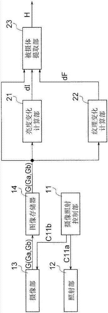
[0061] figure 1 It is a block diagram showing the configuration of the imaging device according to Embodiment 1 of the present invention. The illustrated imaging device includes an imaging and irradiation control unit 11 , an irradiation unit 12 , an imaging unit 13 , a brightness change calculation unit 21 , a texture change calculation unit 22 , a subject extraction unit 23 , and an image memory 14 .
[0062] The imaging device of this embodiment takes, for example, a person as a subject. Specifically, a person's whole body or a part of a person's body such as an upper body, a face, and a hand is used as a subject to extract only the subject from the background.
[0063] The imaging and irradiation control unit 11 outputs a control signal (illumination condition control signal) C11 a for controlling the illumination condition to the irradiation unit 12 , and generates a control signal (imaging condition control signal) C11 b for controlling the imaging condition and outputs...
Embodiment approach 2
[0328] Figure 21 It is a block diagram showing the configuration of an imaging device according to Embodiment 2 of the present invention. Figure 21 The camera shown with the figure 1 The imaging devices shown are substantially the same, except that a target value calculation unit 24 is added, and an imaging and irradiation control unit 11 b is provided instead of the imaging and irradiation control unit 11 . and figure 1 The same reference numerals denote the same or corresponding parts, and therefore explanations thereof are omitted.
[0329] exist figure 1 In the imaging device shown, the lighting conditions and imaging conditions are fixed, but in the imaging device of the present embodiment, the target value calculation unit 24 calculates By adjusting at least one of the lighting conditions and the imaging conditions, the accuracy of extracting the subject region is improved in response to changes in ambient light or background.
[0330] The adjustment of the lighti...
Embodiment approach 3
[0387] Figure 25 It is a block diagram showing the configuration of an imaging device according to Embodiment 3 of the present invention. Figure 25 The camera shown with the Figure 21 The imaging device shown is substantially the same, except that it has an imaging and irradiation control unit 11c, a brightness change calculation unit 21c, a texture change calculation unit 22c, an object extraction unit 23c, and a target value calculation unit 24c instead of Figure 21 The imaging and irradiation control unit 11b, the brightness change calculation unit 21, the texture change calculation unit 22, the subject extraction unit 23, and the target value calculation unit 24. and Figure 21 The same reference numerals denote the same or corresponding parts, and therefore explanations thereof are omitted.
[0388] In Embodiment 2, the texture change calculation unit 22 calculates one texture change dF from two images captured under different lighting conditions at different times...
PUM
 Abstract
Description
Claims
Application Information
 - R&D
- Intellectual Property
- Life Sciences
- Materials
- Tech Scout
- Unparalleled Data Quality
- Higher Quality Content
- 60% Fewer Hallucinations
Browse by: Latest US Patents, China's latest patents, Technical Efficacy Thesaurus, Application Domain, Technology Topic, Popular Technical Reports.
© 2025 PatSnap. All rights reserved.Legal|Privacy policy|Modern Slavery Act Transparency Statement|Sitemap|About US| Contact US: help@patsnap.com


