Adjustable punching device applied to workpieces

A stamping device and adjustable technology, applied in the field of workpiece processing, can solve the problems of poor stamping quality, low stamping efficiency, and small application range, and achieve the effects of improving stability, improving stamping quality, and enhancing stamping quality.

Inactive Publication Date: 2017-12-01
ANHUI HAITUO ZHIYONG INTELLIGENT EQUIP CO LTD
View PDF6 Cites 17 Cited by
  • Summary
  • Abstract
  • Description
  • Claims
  • Application Information

AI Technical Summary

Problems solved by technology

[0003] The purpose of the present invention is to provide a machine with reasonable structure design, high work efficiency, wide application range, good versatility, and high stamping quality for the problems of low stamping efficiency, small application range and poor stamping quality in the existing presses. Good adjustable punching unit for workpieces

Method used


Image

  • Adjustable punching device applied to workpieces
  • Adjustable punching device applied to workpieces
  • Adjustable punching device applied to workpieces

Examples


Embodiment 1

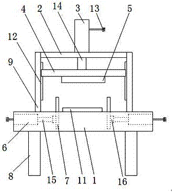
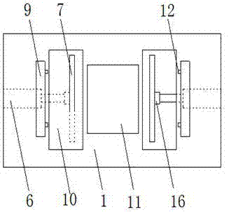
[0017] as attached figure 1 and 2 As shown, an adjustable stamping device applied to workpieces includes an operation table 1, a fixed plate 2, a cylinder 3, a slider 4, a pressing block 5, a cylinder 2 6 and a fastening plate 7, and is characterized in that: The operating platform 1 is arranged on the bracket 8, and the operating platform 1 is provided with a vertical plate 9, a limit groove 10, and a bearing platform 11, and the fixed plate 2 is arranged between the vertical plate 9 and the vertical plate 9, so The cylinder one 3 is arranged on the fixed plate 2, and the power cord 13 and the piston rod one 14 are arranged on the cylinder one 3, and the slider 4 is arranged on the piston rod one 14 and the power cord 13. Block 5 is arranged on slide block 4, and described cylinder 2 6 is arranged in console 1, and is provided with power line 13, piston rod 2 15 on cylinder 2 6, and described fastening plate 7 is arranged on the limit In the groove 10, the fastening plate 7...

Embodiment 2

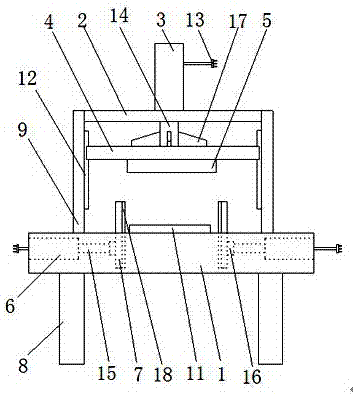
[0023] as attached image 3 As shown, an adjustable stamping device applied to workpieces includes an operation table 1, a fixed plate 2, a cylinder 3, a slider 4, a pressing block 5, a cylinder 2 6 and a fastening plate 7, and is characterized in that: The operating platform 1 is arranged on the bracket 8, and the operating platform 1 is provided with a vertical plate 9, a limit groove 10, and a bearing platform 11, and the fixed plate 2 is arranged between the vertical plate 9 and the vertical plate 9, so The cylinder one 3 is arranged on the fixed plate 2, and the power cord 13 and the piston rod one 14 are arranged on the cylinder one 3, and the slider 4 is arranged on the piston rod one 14 and the power cord 13. Block 5 is arranged on slide block 4, and described cylinder 2 6 is arranged in console 1, and is provided with power line 13, piston rod 2 15 on cylinder 2 6, and described fastening plate 7 is arranged on the limit In the groove 10, the fastening plate 7 is con...


PUM


Abstract

The invention discloses an adjustable stamping device applied to workpieces, which includes an operation table, a fixed plate, a cylinder one, a slider, a pressing block, a cylinder two and a fastening plate, and is characterized in that the operation table is set on the bracket Above, the fixed plate is set between the vertical plate and the vertical plate, the cylinder one is set on the fixed plate, the slider is set on the piston rod one and the power cord, and the pressing block is set on the slide On the block, the cylinder 2 is set in the console, and the fastening plate is set in the limit groove. In the present invention, a limiting groove is arranged on the operating table, and a fastening plate connected with the piston rod 2 of the cylinder 2 is arranged in the limiting groove, and the workpiece to be stamped is placed on the bearing platform, and the workpiece can be clamped by the fastening plate , improve the stability of the workpiece in the stamping process, enhance the stamping quality of the workpiece, set a limit rod on the vertical plate, through the limit rod, the stability of the slider in the process of rising or falling can be improved, and the stamping quality of the workpiece can be further improved .

Description

technical field [0001] The invention relates to the technical field of workpiece processing, in particular to an adjustable stamping device applied to workpieces. Background technique [0002] At present, when the workpiece is being processed, the workpiece is sometimes made into a fixed shape. In the past, the workpiece was beaten by hand, which has low processing efficiency, low processing quality, and safety issues. For example, the patent application number 201710416469.7 discloses a stamping machine that can fix the bearing, which solves the problem that the stamping machine cannot fix the bearing, but it has the problems of low stamping efficiency, small application range, and poor stamping quality. question. Contents of the invention [0003] The purpose of the present invention is to provide a machine with reasonable structure design, high work efficiency, wide application range, good versatility, and high stamping quality for the problems of low stamping efficien...

Claims


Application Information

Patent Timeline
Patent Type & Authority Applications(China)
IPC IPC(8): B21D22/02B21D43/00
CPCB21D22/02B21D43/003
Inventor 冯继友梁振华
Owner ANHUI HAITUO ZHIYONG INTELLIGENT EQUIP CO LTD
Why Eureka
Try Eureka