Underwater robot capable of changing power driving direction

An underwater robot and power-driven technology, applied in the field of robotics, can solve problems such as complex actions that are difficult to meet

Inactive Publication Date: 2017-12-01
苏州大贝岩电子科技有限公司
View PDF5 Cites 3 Cited by
  • Summary
  • Abstract
  • Description
  • Claims
  • Application Information

AI Technical Summary

Problems solved by technology

[0002] For existing underwater robots, the power direction of the drive mechanism is generally fixed relative to the direction of the body, and the direction of travel is changed by changing the direction of the rudder. This method of travel is difficult to meet the needs of more complex actions.

Method used


Image

  • Underwater robot capable of changing power driving direction
  • Underwater robot capable of changing power driving direction
  • Underwater robot capable of changing power driving direction

Examples


Embodiment 1)

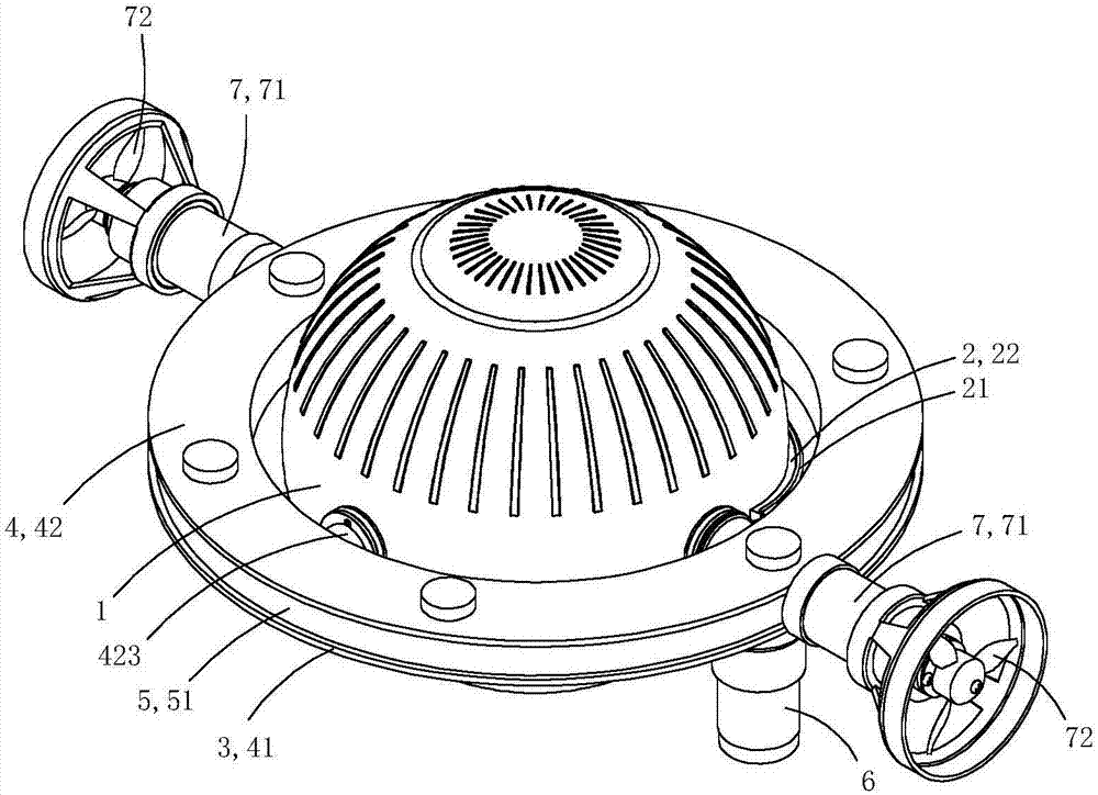
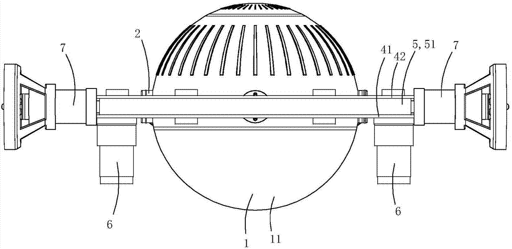
[0014] This embodiment is a kind of underwater robot that can change the driving direction of power, see Figure 1 to Figure 3 As shown, it includes a housing 1, a camera module built in the housing and a driving mechanism 3 for driving the housing to move.

[0015] The overall shape of the casing is spherical, and the bottom of the casing is provided with a transparent hemispherical observation chamber 11; The light on the pan / tilt mechanism (not shown in the figure). The camera is fixedly arranged at the bottom of the pan-tilt mechanism, facing the transparent wall of the hemispherical observation room.

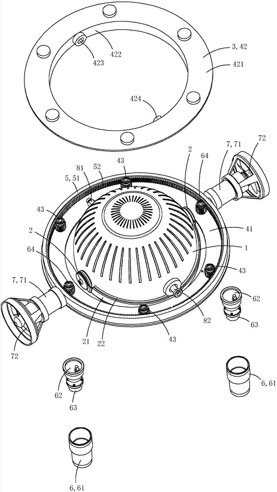
[0016] The drive mechanism 3 includes a ring base 4 that is rotatably arranged on the housing, a ring gear 5 that is rotatably provided on the ring base, a gear drive mechanism 6 that is used to drive the ring gear to rotate on the ring base, and a ring gear that is arranged on the ring gear. Two propeller drives7.

[0017] The annular base includes a base 41 and a cover...


PUM


Abstract

The invention discloses an underwater robot capable of changing the driving direction of power, which comprises a casing and a driving mechanism for driving the casing to move; The ring gear, the gear drive mechanism for driving the ring gear to rotate on the ring base, and the propeller driver arranged on the ring gear; The propeller drive motors and the propellers arranged on the outer wall of the drive chamber are rotated, and each propeller drive motor drives a corresponding propeller to rotate. The invention can realize 360-degree driving in any direction without dead angle.

Description

technical field [0001] The invention belongs to the technical field of robots, and in particular relates to an underwater robot capable of changing the driving direction of power. Background technique [0002] In the existing underwater robots, the power direction of the driving mechanism is generally fixed relative to the direction of the main body, and the direction of travel is changed by changing the direction of the rudder, which is difficult to meet the needs of more complex actions. Contents of the invention [0003] The object of the present invention is to provide an underwater robot capable of changing the driving direction of power. [0004] The technical solution for realizing the object of the present invention is: an underwater robot capable of changing the driving direction of power, including a casing and a driving mechanism for driving the casing to move; The ring gear on the ring base, the gear drive mechanism for driving the ring gear on the ring base, ...

Claims


Application Information

Patent Timeline
IPC IPC(8): B63G8/00B63C11/52
CPCB63G8/001B63C11/52B63G2008/002
Inventor 黄建中
Owner 苏州大贝岩电子科技有限公司
Why Eureka
Try Eureka