
Thermal mechanical fatigue test system and method for performing hollow turbine blade superposed high-cycle vibration

A technology of thermomechanical fatigue and turbine blades, which is applied to the thermomechanical fatigue test system and field of hollow turbine blades with superimposed high-cycle vibration, can solve the problems of inability to adjust the stress distribution of the blade body, the inability to adjust the stress state of the turbine blades, and the inability to achieve turbine Blade thermomechanical fatigue test and other issues, to ensure the safety and accuracy of testing the life of turbine blades

Active Publication Date: 2017-12-01
BEIHANG UNIV
View PDF10 Cites 32 Cited by
  • Summary
  • Abstract
  • Description
  • Claims
  • Application Information

AI Technical Summary

Problems solved by technology

However, this solution is aimed at the mortise joint structure of the turbine, and cannot adjust the stress distribution of the real blade body
[0005] To sum up, on the basis of the existing technical conditions, it is impossible to adjust the stress state of the turbine blade assessment section and apply high and low cycle loads at the same time, so it is impossible to realize the thermomechanical fatigue test of the superimposed high cycle vibration of the turbine blade

Method used


Image

  • Thermal mechanical fatigue test system and method for performing hollow turbine blade superposed high-cycle vibration
  • Thermal mechanical fatigue test system and method for performing hollow turbine blade superposed high-cycle vibration
  • Thermal mechanical fatigue test system and method for performing hollow turbine blade superposed high-cycle vibration

Examples


Embodiment Construction

[0039] The present invention will be described in detail below in conjunction with the accompanying drawings and embodiments.

[0040] The present invention is mainly aimed at the thermomechanical fatigue test system of superimposed high-cycle vibration of hollow turbine blades, wherein high and low cycle loads are terms in the industry, and low cycle loads are generally large-scale low-frequency loads (amplitude is generally greater than 5kN, and frequency is generally less than 1Hz ), the high-cycle load is generally a small-amplitude high-frequency load (the displacement amplitude is generally less than 1.5mm, and the frequency is generally greater than 10Hz).

[0041] like Figure 16 As shown, the system of the present invention includes five parts: high cycle load loading subsystem, low cycle load loading subsystem, temperature load loading subsystem, cooling subsystem and load coordination control subsystem. The high-cycle load loading subsystem and the low-cycle load l...


PUM


Abstract

The invention relates to a thermal mechanical fatigue test system and method for performing hollow turbine blade superposed high-cycle vibration. The test system comprises a high / low-cycle load loading subsystem, a temperature load loading subsystem, a cooling subsystem and a load coordination control subsystem, wherein the high / low-cycle load loading subsystem is used for independently applying high / low-cycle loads to turbine blades which are stably clamped by a special fixture; the temperature load loading subsystem is used for heating assessment sections of the turbine blades; the cooling subsystem comprises a water cooling part and an air cooling part; the water cooling part is used for cooling in a test process; the air cooling part is used for coordinating a temperature cycle in the test and simulating cooling conditions inside the blades; and the load coordination control subsystem is used for controlling each system to operate in a coordinated manner. According to the test system disclosed by the invention, the stress field, temperature field and vibration conditions in the assessment section service process of the turbine blades and the cooling conditions inside the blades can be simulated, the thermal mechanical fatigue test for superposed high-cycle vibration of the turbine blades is performed, and a guarantee is provided for safe and reliable operations of aircraft engines.

Description

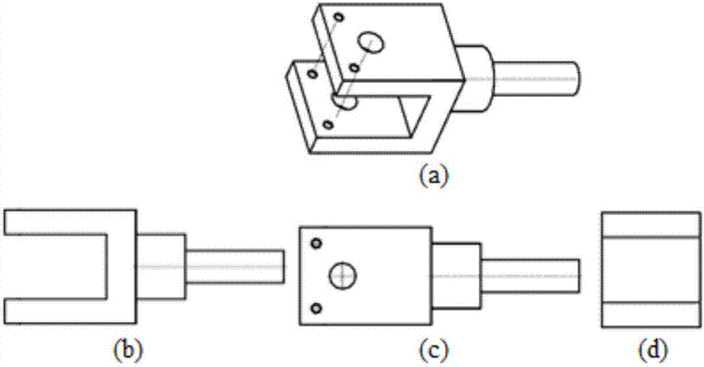
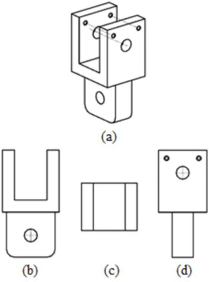
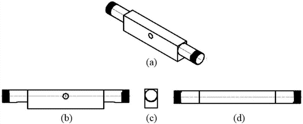
technical field [0001] The invention relates to a composite fatigue test system and method for aeroengine turbine blades, in particular to a thermomechanical fatigue test system and method for a hollow turbine blade with superimposed high-cycle vibration, which can simulate the stress field and temperature of the turbine blade assessment section during service Field, vibration and internal cooling of the blades. On this basis, thermomechanical fatigue tests of hollow turbine blades superimposed with high-cycle vibration can be carried out to test the life of turbine blades and provide guarantee for the safe and reliable operation of aero-engines. It belongs to the technical field of aero-engines . Background technique [0002] Aeroengine turbine blades are subjected to harsh service conditions, not only bearing alternating mechanical loads and thermal loads, but also bearing lateral vibrations induced by aerodynamic loads and their own small-amplitude, high-frequency high-cy...

Claims


Application Information

Patent Timeline
IPC IPC(8): G01N25/20
CPCG01N25/20
Inventor 胡殿印王荣桥张斌马琦航崔金铎田腾跃
Owner BEIHANG UNIV
Learn More