Display driving method and flat panel display

A display driver and display panel technology, applied in static indicators, instruments, etc., can solve the problems of labor-intensive, inability to know the length of time, and complexity.

Active Publication Date: 2020-04-14
CHIPONE TECH BEIJINGCO LTD
View PDF9 Cites 0 Cited by
  • Summary
  • Abstract
  • Description
  • Claims
  • Application Information

AI Technical Summary

Problems solved by technology

[0005] Therefore, if figure 2 As shown, when the default vertical back-end setting value and vertical front-end setting value of the display driver module 21 are different from the time lengths of the vertical back-end area VBP and the vertical front-end area VFP set by the host computer 10, the display driver module 21 will The display data output interval VDP of the generated data enable signal DE does not correspond to the display data area DA of the picture frame, which causes the picture displayed by the display panel 22 to go upward (the time length of the vertical rear end area is greater than the corresponding value of the rear end setting value) time) or downward offset (the time length of the vertical rear end area is less than the time corresponding to the rear end setting value)
[0006] In order to solve the above problems, since the time length of the vertical back end area VBP and the vertical front end area VFP set by the host computer 10 cannot be known, the existing method is to randomly adjust the vertical back end of the display driver module 21 manually by the engineer on site. Set value and vertical front set value until the display panel 22 normally displays the picture
However, since the time lengths of the vertical back-end area VBP and the vertical front-end area VFP set by the host 10 of different types or different models of mobile terminals 1 are often not the same, engineers must focus on different types or models in the production stage. The mobile terminal 1 manually adjusts the default vertical back-end setting value and vertical front-end setting value in the display driver module 21. This process is not only complicated, time-consuming and labor-intensive

Method used


Image

  • Display driving method and flat panel display
  • Display driving method and flat panel display
  • Display driving method and flat panel display

Examples


Embodiment Construction

[0057] Before the present invention is described in detail, it should be noted that in the following description, similar components are denoted by the same numerals.

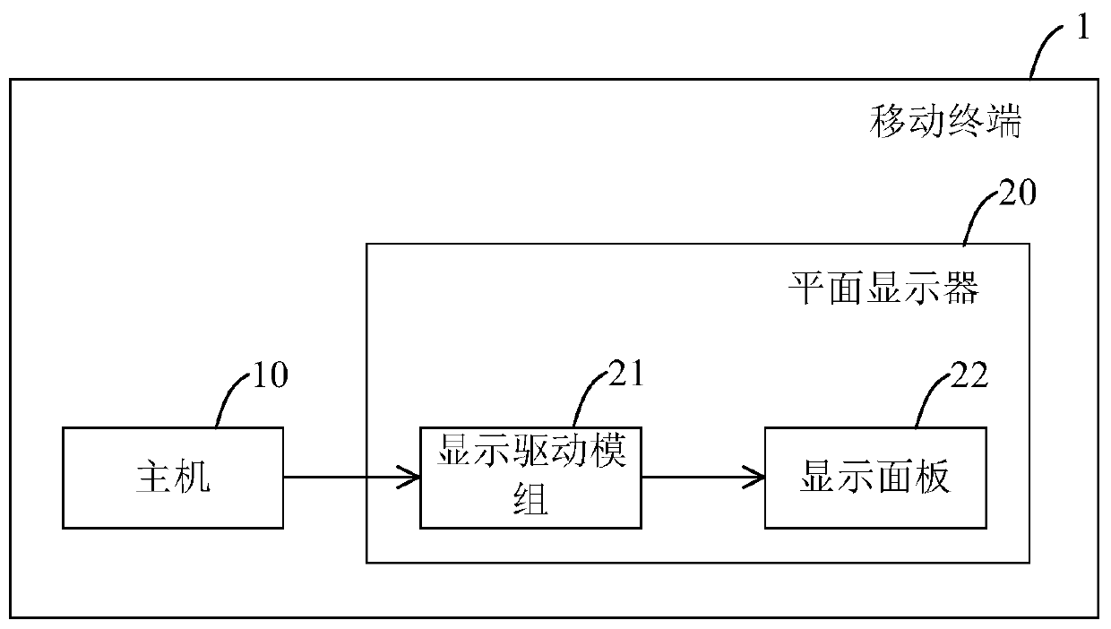
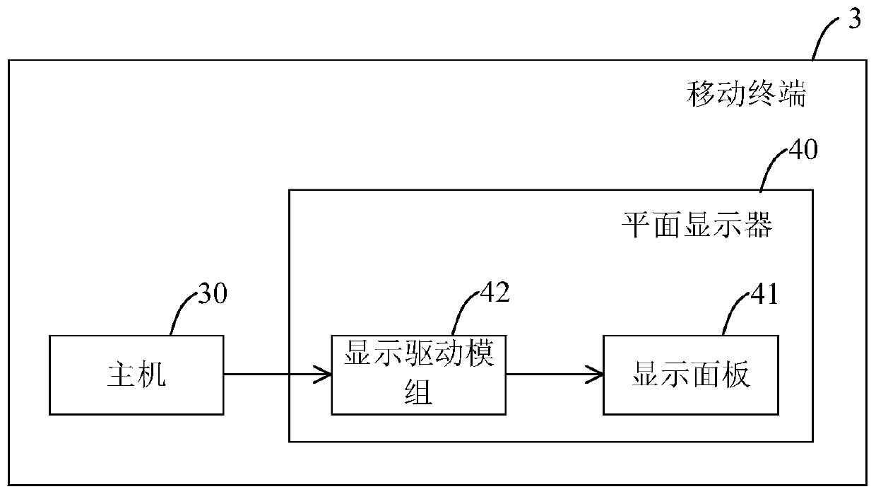
[0058] refer to Figure 3 to Figure 6 , is an embodiment of the display driving method of the present invention, which is applied to such as image 3 As shown, the mobile terminal 3 comprising the host 30 and the flat panel display 40 of the present invention, the embodiment of the flat panel display 40 mainly includes a display panel 41 and a display driver module 42 that drives the display panel 41, and as Figure 4 As shown, in this embodiment, the display panel 41 has a source driver (Gate Driver on Array, GOA for short) 411 built therein. The display driver module 42 mainly includes a transmission interface 43, a decoder 44 electrically connected to the transmission interface 43, a timing controller 45 electrically connected to the decoder 44 and a source driver 411, and a timing controller 45 and a displ...


PUM


Abstract

The invention discloses a display driving method. The method includes the following steps: a display driving module detecting front N picture frames (N is an integer and N is greater than or equal to 2) in an image signal which is transmitted by a DSI interface of the MIPI of a main computer, computing a first time length of a vertical rear end region and a second time length of a vertical front end region of each of the front N picture frames, and if it is determined that the first time lengths are of the same length and are different from a preset vertical rear end value, and the second time lengths are of the same length and are different from a preset vertical front end value, updating the vertical rear end value with the first time lengths and updating the vertical front end value with the second time lengths, and based on a vertical synchronous signal, a vertical rear end set value and a vertical front end set value, outputting the display data of each picture frame to a display panel.

Description

【Technical field】 [0001] The present invention relates to a display driving method, in particular to a display driving method for image signals transmitted in Display Serial Interface (DSI) format of Mobile Industry Processor Interface (MIPI). 【Background technique】 [0002] see figure 1 As shown, an existing mobile terminal 1, such as a mobile phone, a tablet computer, etc., displays images in a way that the host computer 10 uses a Display Serial Interface (Display Interface) of the Mobile Industry Processor Interface (MIPI) for short. Serial Interface, referred to as DSI) (hereinafter referred to as the display serial interface of MIPI) transmits image signals including multiple frame data to the display driver module 21 of the flat panel display 20, and as figure 2 As shown, the display driving module 21 will generate a vertical synchronous signal VS according to the image signal, so as to control the display frequency of the display panel 22 of the flat-panel display 2...

Claims


Application Information

Patent Timeline
Patent Type & Authority Patents(China)
IPC IPC(8): G09G3/20
CPCG09G3/20
Inventor 徐勤凯黄义斌
Owner CHIPONE TECH BEIJINGCO LTD
Why Eureka
Try Eureka