
Assembling and adjusting method for high-precision swing mirror shafting component

A high-precision, mirror shaft technology, applied in the field of high-precision swing mirror shaft assembly adjustment technology, can solve the problems of high cost, difficult to guarantee at the same time, time-consuming and labor-intensive, etc., to improve reliability, reduce adjustment difficulty, save adjustment The effect of school time

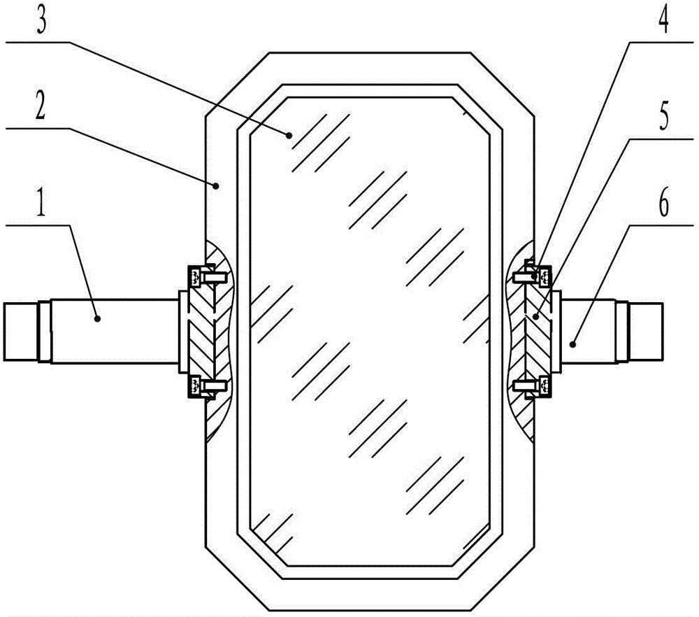
Inactive Publication Date: 2013-01-16
XI'AN INST OF OPTICS & FINE MECHANICS - CHINESE ACAD OF SCI
View PDF5 Cites 1 Cited by
  • Summary
  • Abstract
  • Description
  • Claims
  • Application Information

AI Technical Summary

Problems solved by technology

This kind of adjustment is not only very time-consuming, laborious and expensive, but also enlarges the size of the left and right end holes of the swing mirror base in order to meet the adjustment accuracy requirements of the swing mirror shaft assembly, but reduces the reliability of the shaft hole fit.
[0020] (3) Even if the assembly of the oscillating mirror base and the left and right shafts has been adjusted, it is very difficult to ensure the coaxiality of the left and right shafts, the perpendicularity between the end faces of the left and right shafts and the rotation centerline of the left and right shafts, and the placement groove of the oscillating mirror base The four indicators of parallelism and vertical distance to the left and right axis rotation centerline all meet the requirements, and often need to be compromised

Method used


Image

  • Assembling and adjusting method for high-precision swing mirror shafting component
  • Assembling and adjusting method for high-precision swing mirror shafting component

Examples


Embodiment Construction

[0038] The combined adjustment method of high-precision swing mirror shaft system components includes the following steps:

[0039] Step 1: rough machining the left end hole of the swing mirror base, rough machining the right end hole of the swing mirror base, rough machining the swing mirror placement groove of the swing mirror base; rough machining the left shaft, rough machining the right shaft;

[0040] Step 2: Semi-finishing the left end hole of the swing mirror base, semi-finishing the right end hole of the swing mirror base, semi-finishing the swing mirror placement groove of the swing mirror base; semi-finishing the left axis, semi-finishing the right axis;

[0041] Step 3: Install the left shaft in the left end hole of the swing mirror base, install the right shaft in the right end hole of the swing mirror base, install the shaft fastening screws, and form the swing mirror assembly to be finished;

[0042] Step 4: Finish machining the left axis and the right axis of t...


PUM


Abstract

The invention provides an assembling and adjusting method for a high-precision swing mirror shafting component. The assembling and adjusting method includes the steps: (1) roughly machining each part; (2) subjecting each part to semi-finish machining; (3) assembling all the parts to form a swing mirror component to be accurately machined; (4) respectively accurately machining a left shaft and a right shaft to enable the sizes, cylindricity, end face verticality and coaxiality of the left shaft and the right shaft to meet design requirements, and then accurately machining a swing mirror placing groove of a swing mirror seat according to a left-right shaft rotary center line determined by the left shaft and the right shaft of the swing mirror component at the moment to enable the swing mirror mounting face position and the left-right shaft rotary center line to meet the design requirements on parallelism and perpendicular distance; and (5) drilling and reaming positioning pin holes on the left and on the right of a swing mirror, and performing trial assembly of shaft positioning dowels. By the assembling and adjusting method for the high-precision swing mirror shafting component, an adjusting operation process is simplified, adjusting operation difficulty can be further lowered with adjusting precision improved, and adjusting efficiency is improved.

Description

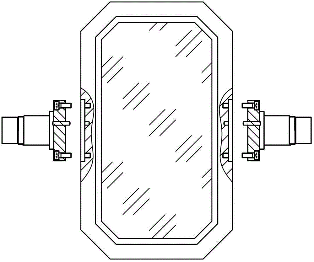
technical field [0001] The invention relates to an adjustment process of a high-precision pendulum mirror shaft assembly. Background technique [0002] Such as figure 1 , 2 As shown, the high-precision oscillating mirror shaft assembly is generally installed on a bracket, and the left and right shafts are respectively supported and rotated by bearing groups. Shaking and angle measurement accuracy requirements are high. [0003] The high-precision swing mirror shaft assembly generally consists of left shaft 1, swing mirror base 2 (stage), swing mirror 3 (equipped with instruments), and right shaft 6. The left axis, right shaft and swing mirror base rely on shaft fastening screws 4 connection, left shaft, right shaft and swing mirror seat respectively determine the relative position by two shaft positioning pins 5, guarantee the relative form and position requirement among left shaft, right shaft, swing mirror seat three. The usual technical indicators are: [0004] 1) Th...

Claims


Application Information

Patent Timeline
IPC IPC(8): B23P13/00
Inventor 杨宾宏邓小国李华彭小强
Owner XI'AN INST OF OPTICS & FINE MECHANICS - CHINESE ACAD OF SCI
Learn More