Microwave composite heating furnace

A combined heating and microwave technology, applied in microwave heating, electric furnace heating, lighting and heating equipment, etc., can solve the problems of increasing device cost and operating cost, increasing output devices, etc., to improve reaction efficiency and energy efficiency, and increase freedom degree, high heat resistance effect

Inactive Publication Date: 2017-12-01
PRADEEP METALS +1
View PDF6 Cites 2 Cited by
  • Summary
  • Abstract
  • Description
  • Claims
  • Application Information

AI Technical Summary

Problems solved by technology

[0032] Therefore, in order to provide a sufficient microwave effect, it is necessary to solve the disadvantage of using a device that only increases the output, thereby increasing the device cost and operating cost

Method used


Image

  • Microwave composite heating furnace
  • Microwave composite heating furnace
  • Microwave composite heating furnace

Examples


Embodiment 1

[0060] The first embodiment of the microwave composite heating furnace of the present invention will be described below with reference to the accompanying drawings.

[0061] The structure of microwave composite heating furnace

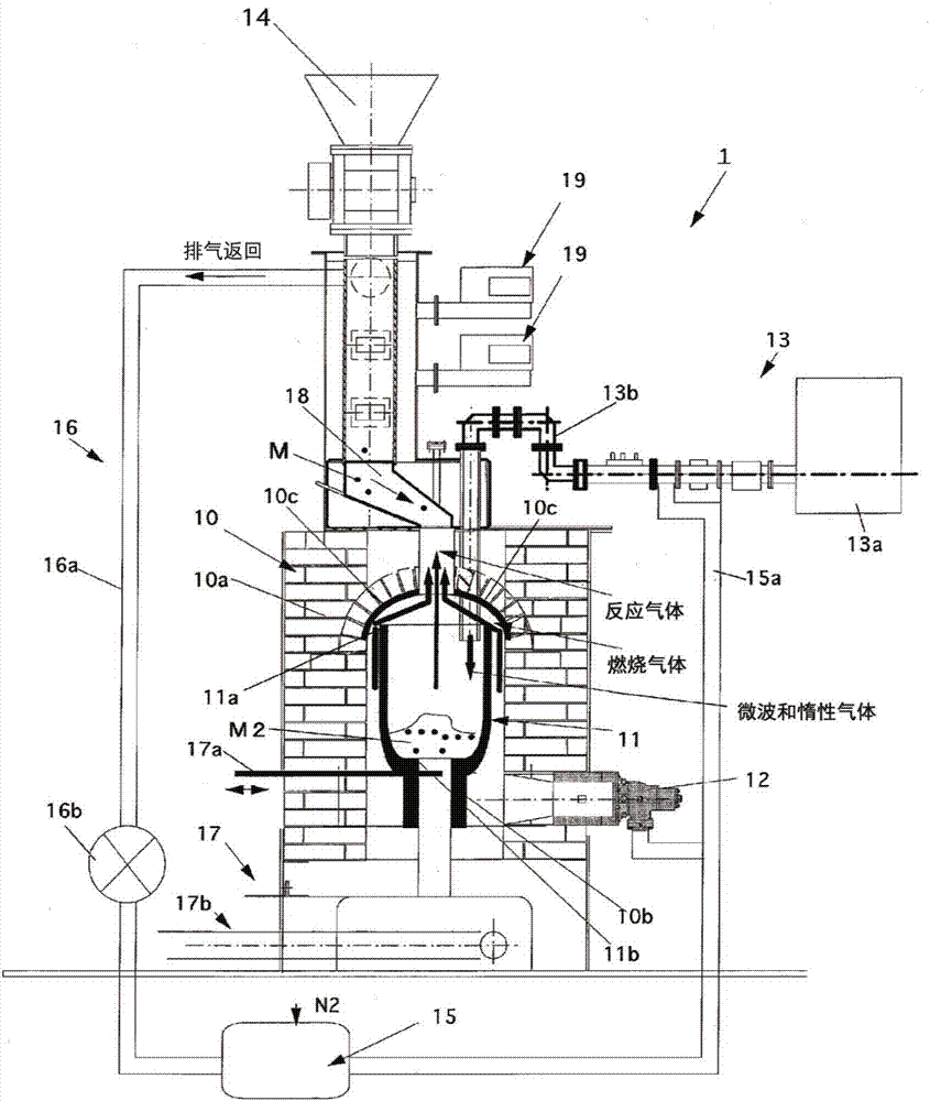
[0062] like figure 1 As shown, the microwave composite heating furnace 1 includes: a housing 10; a heating container 11, which is located inside the housing 10, stores a heated object therein, and heats the heated object; a heating unit 12 for heating The heating container 11 is heated externally; the microwave irradiation device 13; the heated object supply device 14 is used to supply the heated object into the heating container 11; the gas introduction unit 15 is used to introduce gas to adjust the temperature in the heating container 11 gas; a gas collecting unit 16 for collecting and treating processing gas generated when a heated object is heat-treated; and a control device not shown.

[0063] The housing 10 includes a refractory wall 10a forme...

Embodiment 2

[0099] The second embodiment of the microwave composite heating furnace of the present invention will be described below with reference to the accompanying drawings.

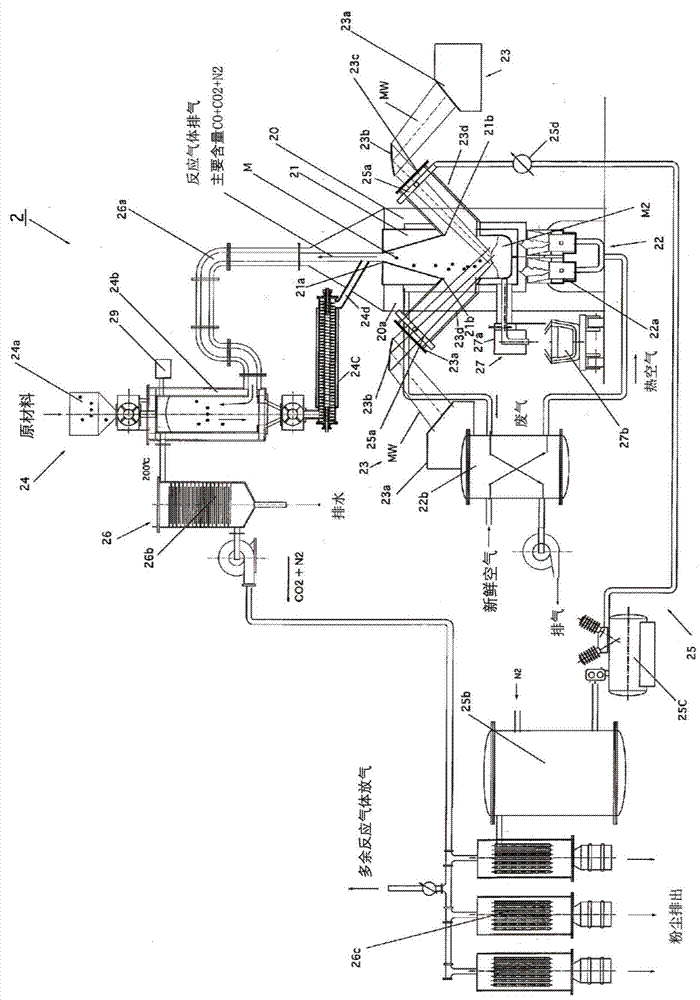
[0100] The microwave composite heating furnace 2 comprises: a housing 20; a heating container 21, which is arranged in the housing 20, and stores and heats objects to be heated; a heating unit 22, which is used to externally heat the heating container 21; a microwave irradiation device 23; the heated object supply device 24 is used to supply the heated object into the heating container 21; the gas introduction unit 25 is used to introduce gas so as to adjust the gas in the heating container 21; the gas collection unit 26 is used to collect and processing gas generated when a heated object is heat-treated; and a control device not shown.

[0101]The housing 20 is made of a refractory wall 20a formed of insulating material such as refractory bricks, and stores the heating container 21 therein.

[0102] The heatin...


PUM


Abstract

The present invention addresses the problem of providing a heating furnace that sufficiently exhibits the microwave effect produced by microwave heating and allows economical heating taking advantage of the characteristics of each heating method. The provided microwave composite heating furnace (1) is equipped with: a housing (10); a heating container (11) for accommodating and heating an object to be heated; a heating means (12) for heating the heating container (11) from the outside; a microwave irradiation device (13); a to-be-heated object supplying device (14) that supplies the object to be heated to the inside of the heating container (11); a gas introducing means (15) for introducing gas into the heating container (11); and a gas recovery means (16) for recovering the gas generated when heating the object to be heated. The heating container (11) comprises a material that has high electrical conductivity so as to reflect microwaves and confine the microwaves inside and that has high heat resistance so as not to react with the heated object, thereby confining microwaves irradiated into the heating container (11) not through the outer wall of the heating container, and allowing an improvement in electromagnetic field density.

Description

technical field [0001] The present invention relates to a microwave composite heating furnace for heating an object to be heated by using a combination of microwaves and external heating such as a burner. Background technique [0002] It has been known since the 1980s that high power microwaves are emitted onto heated objects to heat them in order to provide, for example: [0003] (1) lower reaction temperature; [0004] (2) Shorter reaction time; [0005] (3) High purity material is produced (reaction selectivity). [0006] These properties are different from those chemical and physical properties obtained by conventional heating by flame or high temperature gas. These properties are known as the "microwave effect", which is caused by the direct action of microwave electromagnetic energy on the molecular structure of a substance before the electromagnetic energy is released as heat. There have been many attempts in many fields to apply this effect. [0007] like Figur...

Claims


Application Information

Patent Timeline
Patent Type & Authority Applications(China)
IPC IPC(8): F27B14/04F27B14/10F27B14/14F27D11/12H05B6/64
CPCF27B14/14F27B14/06F27B14/061F27D99/0006H05B6/647F27D2099/0026F27D2099/0028F27D11/12H05B6/80F27B14/04H05B6/64F27B14/10
Inventor 佐藤元泰普拉迪普·戈亚尔伊藤響樫村京一郎永田和宏施瓦南德·博卡
Owner PRADEEP METALS
Why Eureka
Try Eureka