Resonance device
A technology of resonators and electrodes, applied in piezoelectric/electrostrictive/magnetostrictive devices, electrical components, impedance networks, etc., can solve problems such as the influence of the lower electrode and the change of the resonant frequency of the resonator, and achieve a stable resonant frequency Effect
- Summary
- Abstract
- Description
- Claims
- Application Information
AI Technical Summary
Problems solved by technology
Method used
Image

Examples
no. 1 approach
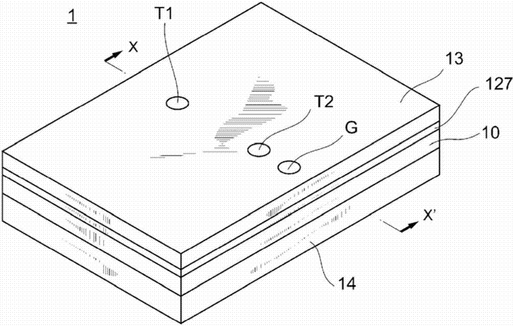
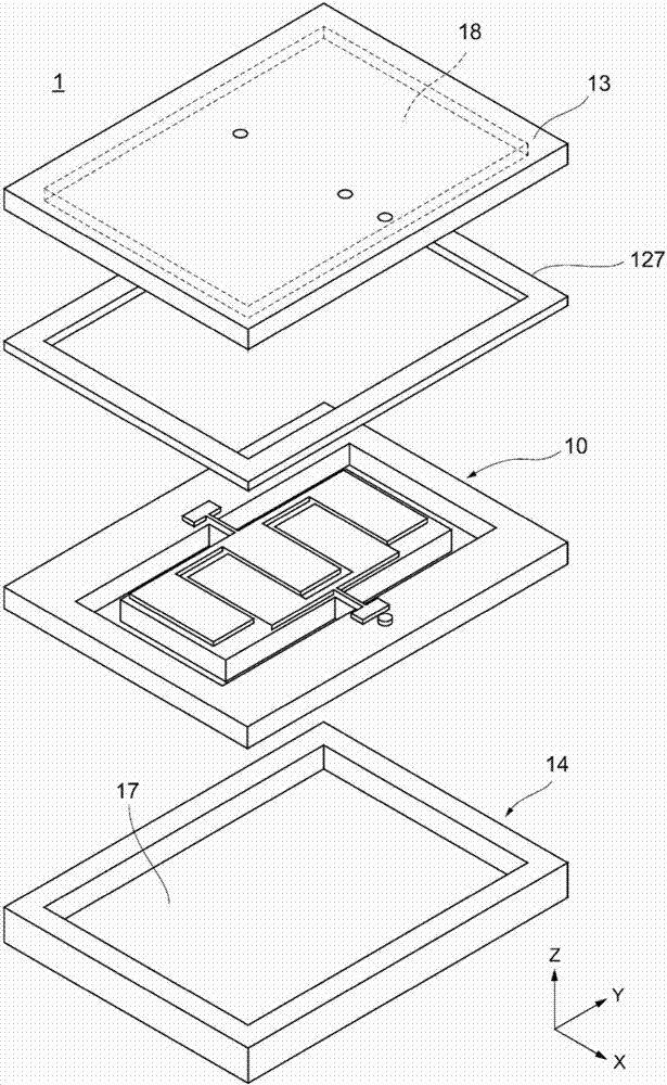
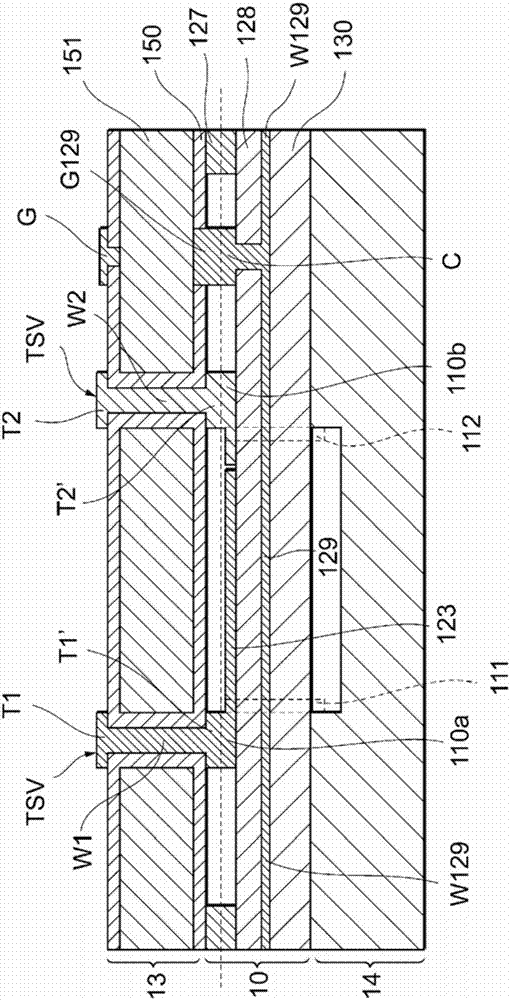
[0034] Hereinafter, a first embodiment of the present invention will be described with reference to the drawings. figure 1 It is a perspective view schematically showing the appearance of the resonance device 1 according to the first embodiment of the present invention. in addition, figure 2 It is an exploded perspective view schematically showing the structure of the resonance device 1 according to the first embodiment of the present invention. in addition, image 3 yes figure 1 XX' section view.
[0035] This resonance device 1 includes a resonator 10 , and an upper cover 13 and a lower cover 14 that sandwich and seal the resonator 10 and form a vibration space in which the resonator 10 vibrates. The resonator device 1 is constituted by sequentially laminating and bonding the lower cover 14 , the resonator 10 , the bonding portion 127 (an example of a bonding layer), and the upper cover 13 .
[0036] The resonator 10 is a MEMS vibrator manufactured using MEMS technolog...
no. 2 approach
[0101] After the second embodiment, the description of the common cases with the first embodiment will be omitted, and only the differences will be described. In particular, the same functions and effects performed by the same structure are not mentioned in turn in each embodiment.
[0102] Image 6 It is a diagram schematically showing an example of a cross-sectional structure of the resonance device 1 of the present embodiment. Hereinafter, the detailed configuration of the resonator device 1 of the present embodiment will be described focusing on differences from the first embodiment.
[0103] (1. Lower cover 14)
[0104] The structure of the lower cover 14 is the same as that of the first embodiment.
[0105] (2. Resonator 10)
[0106] The structure of the resonator 10 is the same as that of the first embodiment.
[0107] (3. Joint 127)
[0108] The structure of the joint portion 127 is the same as that of the first embodiment.
[0109] (4. Upper cover 13)
[0110]...
no. 3 approach
[0113] Figure 7 It is a figure which briefly shows an example of the cross-sectional structure of the resonator 10 of this embodiment. Hereinafter, points of difference from the first embodiment in the respective configurations of the resonator 10 of the present embodiment will be described.
[0114] (1. Lower cover 14)
[0115] The structure of the lower cover 14 is the same as that of the first embodiment.
[0116] (2. Resonator 10)
[0117] In the present embodiment, a part of the piezoelectric film 128 of the holding portion 11 formed at the bonding position of the holding portion 11 and the bonding portion 127 is removed by processing such as etching. The portion where the piezoelectric film 128 is removed is filled with metal forming the lower wiring W129 such as molybdenum or aluminum. In this embodiment, the position filled with this metal corresponds to the conductive layer C in the first embodiment.
[0118] The structure of other resonators 10 is the same as t...
PUM
| Property | Measurement | Unit |
|---|---|---|
| Length | aaaaa | aaaaa |
| Width | aaaaa | aaaaa |
| Thickness | aaaaa | aaaaa |
Abstract
Description
Claims
Application Information
 - R&D
- Intellectual Property
- Life Sciences
- Materials
- Tech Scout
- Unparalleled Data Quality
- Higher Quality Content
- 60% Fewer Hallucinations
Browse by: Latest US Patents, China's latest patents, Technical Efficacy Thesaurus, Application Domain, Technology Topic, Popular Technical Reports.
© 2025 PatSnap. All rights reserved.Legal|Privacy policy|Modern Slavery Act Transparency Statement|Sitemap|About US| Contact US: help@patsnap.com