
Photographic reflector mounting support

A technology for installing brackets and reflectors, applied in photography, machine/brackets, optics, etc., can solve the problems of reducing the fatigue of the staff, reducing the quality of photography and shooting, and being unable to meet the adjustment of the height of the first vertical bar, etc., to achieve reduction Tiredness, enhancing shooting efficiency and shooting quality, and avoiding the overall inconvenient effect of moving

Inactive Publication Date: 2017-12-05
广州酷刻科技有限公司
View PDF1 Cites 0 Cited by
  • Summary
  • Abstract
  • Description
  • Claims
  • Application Information

AI Technical Summary

Problems solved by technology

[0002] With the improvement of people's living standards, more and more people like to shoot. In order to better meet the needs of photography, various photographic equipment are often needed in the process of photography. Photographic reflectors are one of the frequently used equipment. For example, the patent with application number 201520803763.X includes a driving rod perpendicular to the base and extending upwards connected to the center of the base, and a turntable is installed on the top of the driving rod. This patent cannot meet the requirements of effective convenience and anti-reflection. Adjust the angle of the board to reduce the fatigue of the staff, but it is still unable to effectively adjust the height of the first vertical bar, and reduce the quality of photography

Method used


Image

  • Photographic reflector mounting support
  • Photographic reflector mounting support
  • Photographic reflector mounting support

Examples


Embodiment Construction

[0017] The following will clearly and completely describe the technical solutions in the embodiments of the present invention with reference to the accompanying drawings in the embodiments of the present invention. Obviously, the described embodiments are only some, not all, embodiments of the present invention. Based on the embodiments of the present invention, all other embodiments obtained by persons of ordinary skill in the art without making creative efforts belong to the protection scope of the present invention.

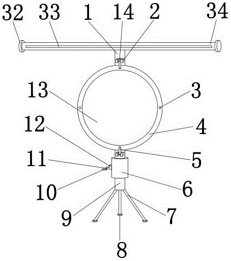
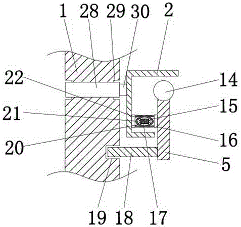
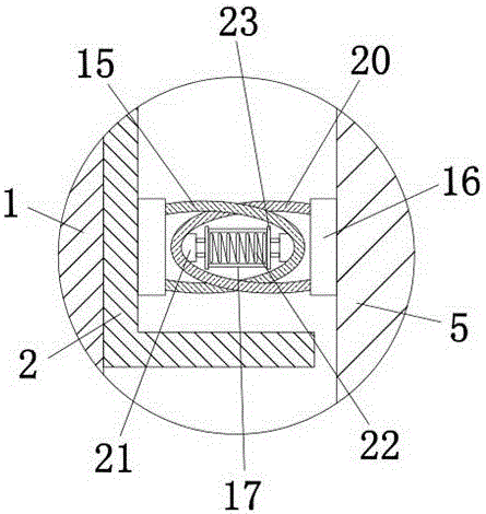
[0018] see Figure 1-5 , the present invention provides a technical solution: a photographic reflector mounting bracket, including a first vertical bar 1 and a second vertical bar 9, the first vertical bar 1 and the second vertical bar 9 are used to fix the fixed concave block 2, the second A vertical bar 1 is connected with the second vertical bar 9 through the cylinder 6, the cylinder 6 is used to fix the connection block 12, and the left side of the cylinde...


PUM


Abstract

The invention discloses a photographic reflector mounting support which comprises a first vertical rod and a second vertical rod. The first vertical rod and the second vertical rod are connected through a cylinder. A crank is arranged on the left side of the cylinder, is connected with the cylinder through a connector block and runs through the cylinder. The outer wall of the crank is connected with a gear in a sleeved manner. An ejector pin is mounted at the bottom of the first vertical rod, and clamping teeth are arranged on the right side of the ejector pin. In application of the photographic reflector mounting support, a connecting rod is shifted and a first pull ring and a second pull ring are driven to compress a compression spring, so that fixing of a reflector is strengthened; the reflector can be rotated in any time by rotating a ring to realize angle regulation so that inconvenience in moving the whole device and influence to service effect of the reflector are avoided; the height of the first vertical rod is regulated effectively by rotating the crank to drive the gear to move on the clamping teeth of the ejector pin, and thus, photographic efficiency and quality is improved and fatigue of work staff is relieved.

Description

technical field [0001] The invention relates to the technical field of mounting brackets for photographic reflective plates, in particular to a mounting bracket for photographic reflective plates. Background technique [0002] With the improvement of people's living standards, more and more people like to shoot. In order to better meet the needs of photography, various photographic equipment are often needed in the process of photography. Photographic reflectors are one of the frequently used equipment. For example, the patent with application number 201520803763.X includes a driving rod perpendicular to the base and extending upwards connected to the center of the base, and a turntable is installed on the top of the driving rod. This patent cannot meet the requirements of effective convenience and anti-reflection. Angle adjustment of the board can reduce the fatigue of the staff, but it is still unable to effectively adjust the height of the first vertical bar and reduce th...

Claims


Application Information

Patent Timeline
Patent Type & Authority Applications(China)
IPC IPC(8): G03B15/06F16M11/04F16M11/10
CPCG03B15/06F16M11/04F16M11/046F16M11/10
Inventor 张帆
Owner 广州酷刻科技有限公司
Learn More