Low-frequency composite sound absorption device

A composite sound-absorbing and low-frequency technology, applied in the direction of sound-generating equipment, instruments, etc., can solve the problem of narrow sound-absorbing frequency band, and achieve the effect of widening sound-absorbing bandwidth and simple structure.

Pending Publication Date: 2017-12-05
BEIJING MUNICIPAL INST OF LABOUR PROTECTION
View PDF7 Cites 14 Cited by
  • Summary
  • Abstract
  • Description
  • Claims
  • Application Information

AI Technical Summary

Problems solved by technology

[0005] The technical problem to be solved by the present invention is to provide a low-frequency composite sound-absorbing device

Method used


Image

  • Low-frequency composite sound absorption device
  • Low-frequency composite sound absorption device

Examples


Embodiment 1

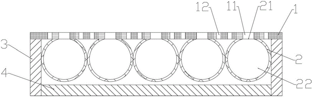
[0026] Such as figure 1 As shown, a low-frequency composite sound-absorbing device provided by an embodiment of the present invention includes a sound-absorbing board 1 and a Helmholtz resonator 2. The sound-absorbing board 1 is provided with a plurality of sound-absorbing holes 12 and unit holes 11. The holes 11 are circular holes or rectangular holes. The number of Helmholtz resonators 2 is equal to the number of unit holes 11, and the plurality of Helmholtz resonators 2 are connected to the plurality of unit holes 11 in a one-to-one correspondence. The Helmholtz resonator 2 includes a cavity 22 and an opening 21 communicating with the cavity. In this embodiment, the cavity 22 is spherical. In addition, the shape of the cavity 22 is not limited, and there are multiple Helmholtz The openings 21 of the resonator 2 all face the front side of the sound absorbing panel 1. When in use, install the low-frequency composite sound-absorbing device on the walls, ceilings, doors and wind...

Embodiment 2

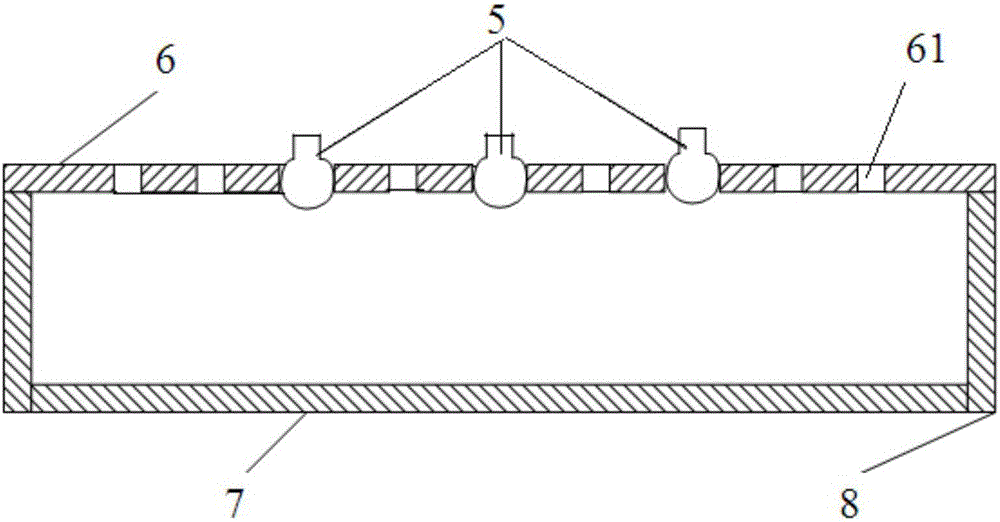
[0034] Such as figure 2 As shown, the structure of the low-frequency composite sound absorbing device provided in this embodiment is similar to that of the low-frequency composite sound absorbing device provided in the embodiment, and the same parts will not be repeated. The difference between the two is: the shape of the unit hole in this embodiment is The shape of the outer contour of the Helmholtz resonator 5 is matched, and a plurality of Helmholtz resonators 5 are embedded in a plurality of unit holes one-to-one, and the opening is located on the side of the front of the sound-absorbing panel. In other words, the end of the Helmholtz resonator 5 with an opening is located on the side of the front of the sound-absorbing board 6, the bottom of the Helmholtz resonator 5 is located on the side of the back of the sound-absorbing board 6, and the opening is Extends outward to form an elongated neck. In addition, the sound-absorbing plate 6 of this embodiment is a perforated pl...


PUM


Abstract

The present invention belongs to the sound processing technical field and relates to a low-frequency composite sound absorption device. The device comprises a sound absorbing plate and Helmholtz resonators; sound absorbing holes and unit holes are formed in the sound absorbing plate, wherein a plurality of unit holes are provided; the number of the Helmholtz resonators is equal to the number of the unit holes; and the Helmholtz resonators are in one-to-one corresponding connection with the unit holes; openings are formed in the Helmholtz resonators; and the openings face the front surface side of the sound absorbing plate. When the low-frequency composite sound absorption device is to be used, the low-frequency composite sound absorption device can be mounted on the wall of a building, a ceiling, a door, a window or the like; one part of sound is absorbed by the sound absorbing holes in the sound absorbing plate, and the other part of the sound enters the cavities of the Helmholtz resonators through the unit holes and the openings of the Helmholtz resonators on the sound absorbing plate and moves in the cavities in a reciprocating manner so as to be dissipated; and the sound absorbing plate and the Helmholtz resonators are utilized to broaden absorption bandwidth; and the structure of the low-frequency composite sound absorption device is simple.

Description

Technical field [0001] The invention relates to the technical field of sound processing, in particular to a low-frequency composite sound absorption device. Background technique [0002] The traditional perforated plate resonant sound-absorbing structure has a closed cavity behind each hole on the perforated plate, which is equivalent to many parallel "Helmholtz" resonators. When the frequency of the incident wave is consistent with the resonance frequency of the system, That is, resonance occurs. At this time, the air reciprocating vibration at the hole of the perforated plate reaches its maximum amplitude, and the friction and damping are also the maximum. The sound energy is converted into heat energy due to viscous loss, that is, the sound energy dissipation reaches the maximum. This is the advantage of the perforated plate resonance absorption structure. But this structure also has its inherent shortcomings. Its main shortcoming is: the frequency selectivity is strong, tha...

Claims


Application Information

Patent Timeline
IPC IPC(8): G10K11/172G10K11/162
CPCG10K11/162G10K11/172
Inventor 盖晓玲邢拓李贤徽张斌
Owner BEIJING MUNICIPAL INST OF LABOUR PROTECTION
Why Eureka
Try Eureka