
A ventilating light guide

A light guide tube and tube body technology, applied in the field of light guide tubes, can solve the problems of poor lighting effect, unsatisfactory use effect, poor ventilation effect, etc., and achieve the effects of improving air quality, accelerating update speed, and increasing flow speed

Active Publication Date: 2020-01-10
CHONGQING TECH & BUSINESS INST
View PDF18 Cites 0 Cited by
  • Summary
  • Abstract
  • Description
  • Claims
  • Application Information

AI Technical Summary

Problems solved by technology

[0005] 1. The ventilation effect is poor. The reason is: it can be seen from its structure that after adopting this "new type of ventilation and daylighting tube", the air in the basement will flow through the vent and enter the inside of the daylighting tube, and then the daylighting Under the action of "the chimney effect of the lighting tube", the air inside the tube will flow out (from the gap between the lighting cover and the fixing ring of the lighting cover) to the outside
It can be seen that the use of this "new type of ventilation and daylighting tube" can only make the air in the basement flow out continuously, which cannot effectively improve the air quality in the basement
[0006] 2. It is invalid or the lighting effect is poor at night. The reason is that this "new type of ventilation and daylighting tube" directly uses natural light for lighting, so the lighting effect is directly determined by natural light, and then at night when natural light is poor, lighting The effect is naturally very poor, and the use effect is not ideal

Method used


Image

  • A ventilating light guide
  • A ventilating light guide
  • A ventilating light guide

Examples


Embodiment Construction

[0071] The present invention will be further described in detail below in conjunction with the accompanying drawings. Wherein, the descriptive terms such as up, down, left, right, etc. are used for the description, with the purpose of helping readers to understand, but not intended to limit.

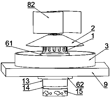
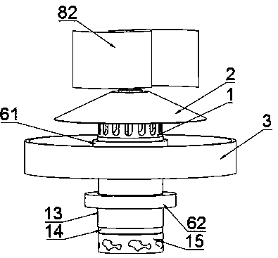
[0072] During specific implementation: if Figure 1 to Figure 9 As shown, a light guide tube that can be exhausted includes a cylinder body 1 and a daylight cover 2, the inner wall of the cylinder body 1 has a reflective layer for conducting natural light, and the top of the cylinder body 1 is fixedly installed with a The daylighting cover 2 for natural light;

[0073] The top side wall of the cylinder 1 is provided with a plurality of air intake holes 11 for air to enter the interior of the cylinder 1, and the lower end of the cylinder 1 has an air outlet 12;

[0074] The daylighting cover 2 is generally in any structure in a dome shape or a conical top shape, and the surroundings of ...


PUM


Abstract

The invention discloses a light guide cylinder capable of exhausting air. The light guide cylinder comprises a cylinder body and a light collection cover. The light guide cylinder is characterized in that a plurality of air inlet holes enabling air to enter the cylinder body are formed in the side wall of the top of the cylinder body, and the lower end of the cylinder body is provided with an air outlet hole; the whole light collection cover is of a dome-shaped structure or a tapered-top-shaped structure, and the periphery of the light collection cover is located below the top of the top of the cylinder body and forms an eave structure; the surface of the inner side face of the light collection cover is provided with a light reflection layer, and a solar power generation panel is laid on the outer side face of the light collection cover; the light guide cylinder further comprises a natural light reflection plate, a controller, a rechargeable battery and an electric light source; and the natural light reflection plate is arranged on the outer surface of a building which is used for enabling the top of the cylinder body to be exposed, the whole natural light reflection plate is in an annular plate shape arranged on the exterior of the cylinder body in a sleeving manner, and the upper surface of the natural light reflection plate is provided with a light reflection layer and used for reflecting natural light to the inner side face of the light collection cover. The light guide cylinder capable of exhausting air has the beneficial effects that the ventilation effect is good, and lighting can also be achieved at night.

Description

technical field [0001] The invention belongs to the field of lighting devices, and in particular relates to a light guide cylinder capable of exhausting wind. Background technique [0002] The light guide tube is a device that uses a highly reflective light guide to introduce sunlight from the outside to the room, and uses natural light to illuminate the room. It is a green, healthy, environmentally friendly, and energy-free lighting product. [0003] Notification number is the patent of CN206131292U, promptly discloses " a kind of novel ventilation daylighting tube ". The "new ventilation and daylighting tube" includes the roof of the basement, the ground and the fixed wall of the light guiding ventilation tube. There are multiple vents on the side and bottom of the light guiding ventilation tube, and the chimney effect of the lighting tube is used to form a hot-pressed Wind, the air enters the lighting tube through the vent, and then passes between the lighting cover and ...

Claims


Application Information

Patent Timeline
Patent Type & Authority Patents(China)
IPC IPC(8): F21S9/02F21S9/03F21S11/00F21S19/00F21V7/00F21V23/00F21V23/02F21V29/508F21V29/67F21V33/00F24F6/04F24F7/007F21W131/10F21Y115/10
CPCF21S9/026F21S9/032F21S11/007F21S19/005F21V7/0016F21V23/003F21V23/023F21V29/508F21V29/677F21V33/0096F21W2131/10F21Y2115/10F24F6/04F24F7/007Y02B10/10Y02B20/72
Inventor 张伟甘诗源张龙
Owner CHONGQING TECH & BUSINESS INST
Learn More