Eye ground camera device based on mobile equipment
A technology of mobile equipment and camera devices, applied in ophthalmoscopes, equipment for testing eyes, photography, etc., can solve the problems of limited promotion and usability, frequent adjustment of positions, restrictions, etc., to achieve the benefits of discovery and treatment, and detection results Clear and accurate, conducive to the effect of early lesions
- Summary
- Abstract
- Description
- Claims
- Application Information
AI Technical Summary
Problems solved by technology
Method used
Image
Examples
Embodiment 1
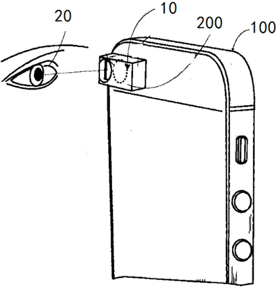
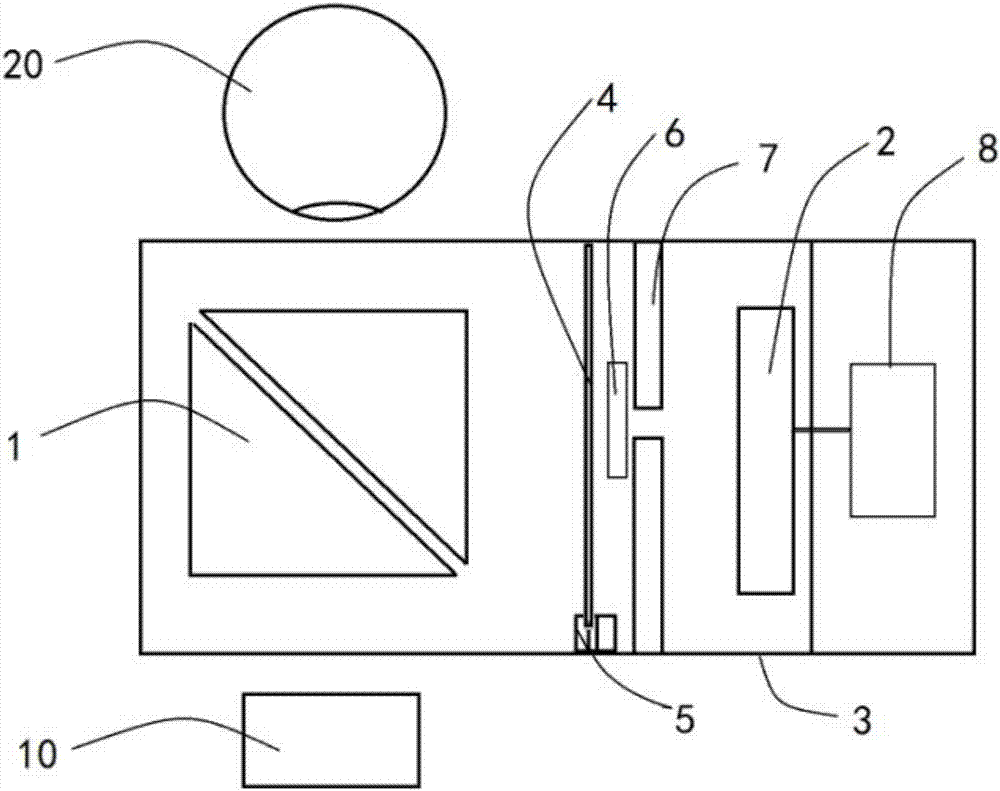
[0036] Such as Figure 1-2 As shown, the present invention provides a mobile device-based fundus imaging device, including a detachably connected mobile device 100 and an optical assembly 200, and the optical assembly 200 includes:
[0037] Optical accessory 1, said optical accessory 1 comprising a partially reflective reflective surface;
[0038] The lighting assembly 2 is located at one end inside the outer frame and is connected to the inner wall of the outer frame. The direction of the light emitted by the lighting assembly 2 faces the optical accessory 1 and is perpendicular to the shooting direction of the camera 10 of the mobile device. The lighting assembly 2. The emitted light shines on the reflective surface and forms a reflected beam pointing to the eyes in the field of view of the camera;
[0039] The coupling device 3 is detachably connected to the mobile device, the coupling device 3 positions the optical accessory 1 at a position corresponding to the camera 10 ...
Embodiment 2
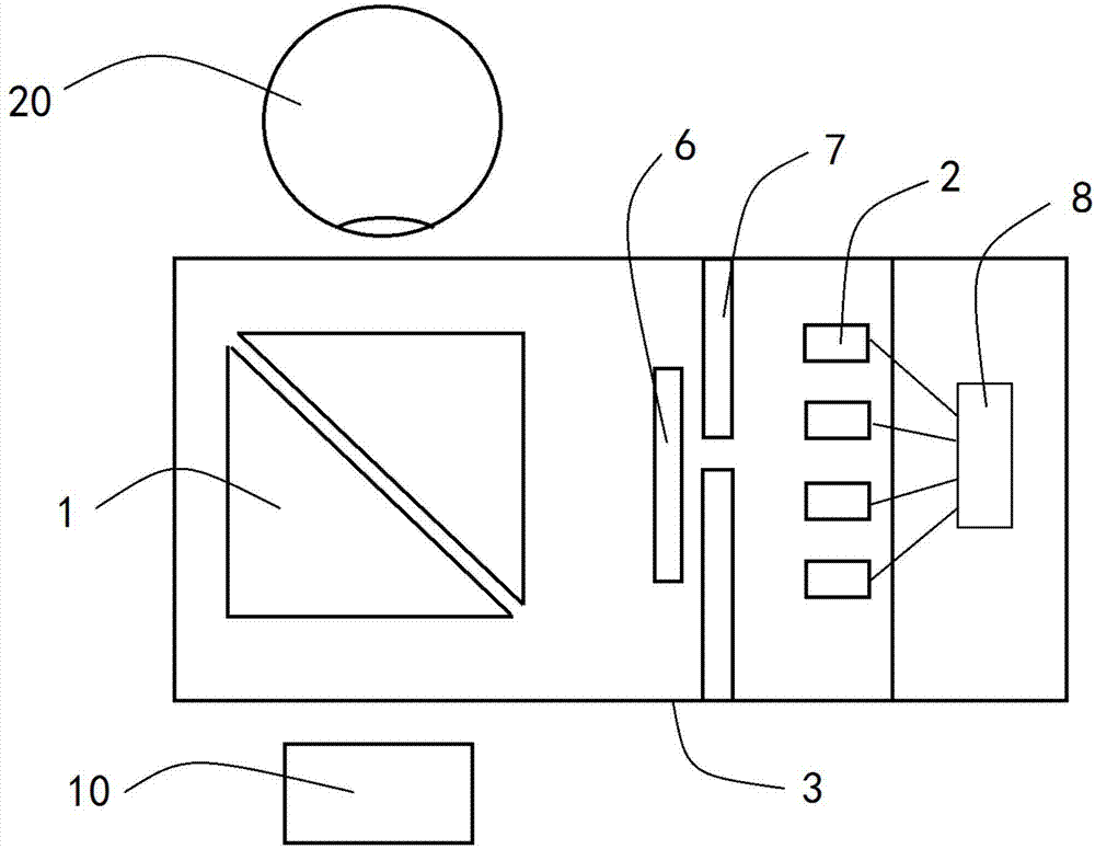
[0050] Such as figure 1 , 3 As shown, the present invention provides a mobile device-based fundus imaging device, including a detachably connected mobile device 100 and an optical assembly 200, and the optical assembly 200 includes:
[0051] Optical accessory 1, said optical accessory 1 comprising a partially reflective reflective surface;
[0052] The lighting assembly 2 is located at one end inside the outer frame and is connected to the inner wall of the outer frame. The direction of the light emitted by the lighting assembly 2 faces the optical accessory 1 and is perpendicular to the shooting direction of the camera of the mobile device. The lighting assembly 2 The emitted light shines on the reflective surface and forms a reflected beam pointing to the eyes within the camera's field of view;
[0053] The coupling device 3 is detachably connected to the mobile device, the coupling device 3 positions the optical accessory 1 at a position corresponding to the camera of the...
Embodiment 3
[0064] Such as figure 1 and 4 As shown, the present invention provides a mobile device-based fundus imaging device, including a detachably connected mobile device 100 and an optical assembly 200, and the optical assembly 200 includes:
[0065] Optical accessory 1, said optical accessory 1 comprising a partially reflective reflective surface;
[0066] The lighting assembly 2 is located at one end inside the outer frame and is connected to the inner wall of the outer frame. The light direction of the lighting assembly 2 is perpendicular to the shooting direction of the camera of the mobile device toward the optical accessory 1 . The lighting assembly 2 The light shines on the reflective surface and forms a reflected beam pointing to the eyes within the camera's field of view;
[0067] The coupling device 3 is detachably connected to the mobile device, the coupling device 3 positions the optical accessory 1 at a position corresponding to the camera of the mobile device, and fix...
PUM
| Property | Measurement | Unit |
|---|---|---|
| Angle | aaaaa | aaaaa |
Abstract
Description
Claims
Application Information
 - R&D
- Intellectual Property
- Life Sciences
- Materials
- Tech Scout
- Unparalleled Data Quality
- Higher Quality Content
- 60% Fewer Hallucinations
Browse by: Latest US Patents, China's latest patents, Technical Efficacy Thesaurus, Application Domain, Technology Topic, Popular Technical Reports.
© 2025 PatSnap. All rights reserved.Legal|Privacy policy|Modern Slavery Act Transparency Statement|Sitemap|About US| Contact US: help@patsnap.com


