Wireless control switching device arranged outside wall switch

A wireless control and switching device technology, applied in the direction of electric switches, electrical components, circuits, etc., can solve the problems of complicated wiring, heavy construction, and not suitable for external use on walls, etc., and achieve the effect of increasing service life

Inactive Publication Date: 2017-12-08
广州酷刻科技有限公司
View PDF1 Cites 3 Cited by
  • Summary
  • Abstract
  • Description
  • Claims
  • Application Information

AI Technical Summary

Problems solved by technology

[0002] Wireless switches are widely used in various fields of life due to their convenience and high degree of intelligence, and wireless switches are divided into non-battery-powered wireless switches and battery-powered wireless switches. When the switch is in use, it needs to be connected to the power supply device separately through the weak wire, and the power supply is supplied through the weak wire, the wiring is complicated, and the construction volume is large. In the prior art, such as the utility model patent with the application number 201520559301. A power supply device for supplying power to the control device. The control device includes a switching value detection input channel, a processor and a wireless transceiver device. The device is connected, the processor generates the switch control command according to the switch signal, and the wireless transceiver device sends the switch control command to the switch control device. Although this utility model is convenient and flexible to use, it cannot be effectively waterproof and dustproof, and is not suitable for external use on the wall.

Method used


Image

  • Wireless control switching device arranged outside wall switch
  • Wireless control switching device arranged outside wall switch
  • Wireless control switching device arranged outside wall switch

Examples


Embodiment Construction

[0016] The following will clearly and completely describe the technical solutions in the embodiments of the present invention with reference to the accompanying drawings in the embodiments of the present invention. Obviously, the described embodiments are only some, not all, embodiments of the present invention. Based on the embodiments of the present invention, all other embodiments obtained by persons of ordinary skill in the art without making creative efforts belong to the protection scope of the present invention.

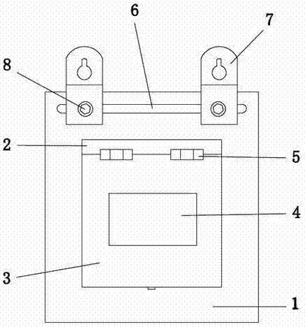
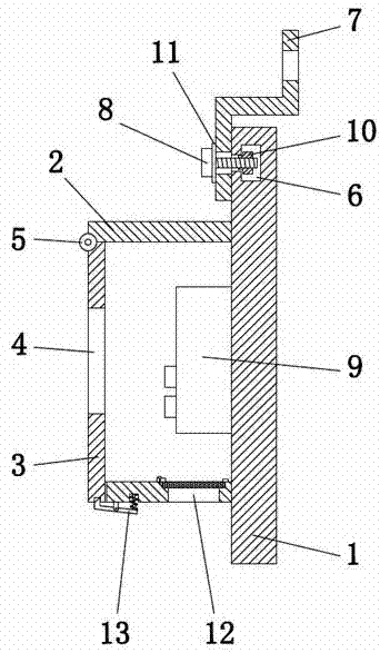
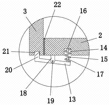
[0017] see Figure 1-4 , the present invention provides a technical solution: a wireless control switch device externally placed on a wall switch, including a backboard 1, a protective cover 2 is installed on the front of the backboard 1, and the protective cover 2 can protect the wireless switch 9 to prevent Water and dust cause damage to the wireless switch 9, increasing the service life of the wireless switch 9, the inner center of the protective cover 2 is...


PUM


Abstract

The invention discloses a wireless control switch device externally placed on a wall switch, comprising a backboard, a protective cover is installed on the front of the backboard, a wireless switch is installed at the inner center of the protective cover, and A cover plate is installed on the front, a locking block is provided on the top left side of the pressure rod, and a card slot is provided at the bottom end of the cover plate. The wireless control switch device externally placed on the wall switch, through the cooperation of the cover plate, the block and the card slot, the protective cover can protect the wireless switch, prevent water and dust from damaging the wireless switch, and increase the service life of the wireless switch , press the right end of the pressure bar upwards, the block is released from the slot, the cover is opened, the wireless switch is operated, and the bolt is loosened to connect with the T-shaped block. Nails, tighten the bolts to connect with the T-block, and the gap between the hanging rings is fixed, which can effectively prevent water and dust, and is suitable for external use on the wall.

Description

technical field [0001] The invention relates to the technical field of wireless switches, in particular to a wireless control switch device externally placed on a wall switch. Background technique [0002] Wireless switches are widely used in various fields of life due to their convenience and high degree of intelligence, and wireless switches are divided into non-battery-powered wireless switches and battery-powered wireless switches. When the switch is in use, it needs to be connected to the power supply device separately through the weak wire, and the power supply is supplied through the weak wire, the wiring is complicated, and the construction volume is large. In the prior art, such as the utility model patent with the application number 201520559301. A power supply device for supplying power to the control device. The control device includes a switch value detection input channel, a processor and a wireless transceiver device. The switch value detection input channel r...

Claims


Application Information

Patent Timeline
IPC IPC(8): H01H9/04H01H9/02
CPCH01H9/047H01H9/02H01H9/0207H01H2009/0292
Inventor 张帆
Owner 广州酷刻科技有限公司
Why Eureka
Try Eureka