Safety energization device for power

An electrification device and safety technology, applied in the direction of the coupling device, parts of the connection device, circuits, etc., can solve the problems of the influence of the electrical equipment, power failure and disengagement of the electrical equipment, etc., to achieve convenient use and prevent accidental power failure , the effect of simple structure

Inactive Publication Date: 2017-12-08
中山市新发装饰工程有限公司
View PDF7 Cites 3 Cited by
  • Summary
  • Abstract
  • Description
  • Claims
  • Application Information

AI Technical Summary

Problems solved by technology

[0002] When the electrical equipment is energized, the power supply head and the power supply seat are used together. The traditional power supply head and the power supply seat use the friction between them to realize the locking of the inserted state, but this locking method is extremely unstable. Due to The post of the power supply head and the power supply head are rigidly fixed, and the power supply seat is also fixed, so when working in the power supply state of the electrical equipment, if you accidentally touch the power supply head, it is easy to disengage from the power supply seat, thereby Accidental power-off of electrical equipment will easily affect the electrical equipment, and also easily cause damage to the power supply head and power supply base, thus affecting the use

Method used


Image

  • Safety energization device for power
  • Safety energization device for power
  • Safety energization device for power

Examples


Embodiment Construction

[0018] Combine below Figure 1-5 The present invention will be described in detail.

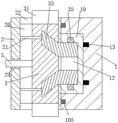
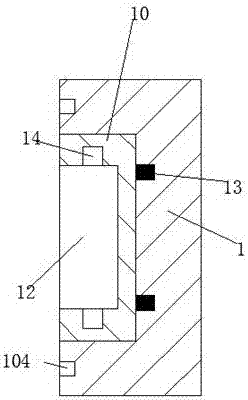
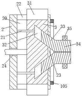
[0019] refer to Figure 1-5 According to an embodiment of the present invention, a safety power supply device for electric power includes a mounting base body 1, a power supply base 10 installed in the mounting base body 1, and a power supply plug device matched with the power supply base 10 The mounting base body 1 is provided with a mounting groove 18 with an opening facing left, the power supply base 10 is slidably installed in the mounting groove 18, and the power supply base 10 is also provided with a slot 12 opening facing left , the upper wall and the lower wall of the slot 12 are provided with a power supply groove 14, and the groove in the right end wall of the installation groove 18 is fixedly installed with a stretching elastic member 13, and the stretching elastic member 13 and the described The power supply seat 10 is fixedly connected; the power supply plug device includes a m...


PUM


Abstract

A safety energization device for power comprises an installation base, a power supply seat and a power supply plug device, wherein the power supply seat is arranged in the installation base, the power supply plug device is matched with the power supply seat, an installation groove with a leftward opening is formed in the installation base, the power supply seat is arranged in the installation groove in a sliding way, a slot with a leftward opening is also formed in the power supply seat, power supply grooves are formed in an upper wall and a lower wall of the slot, a tensile elastic piece is fixedly connected with the power supply seat, the power supply plug device comprises a main body part, a sliding rack and a power supply head, a sliding cavity is formed in the main body part, the sliding rack is arranged in the sliding cavity in a sliding way, two inclining grooves are vertically and symmetrically formed in a right end of the sliding rack, two guide grooves are vertically and symmetrically formed in a left end of the sliding rack, two guide rods are vertically, symmetrically and fixedly arranged on a left end wall of the sliding cavity, right ends of the guide rods extend to the guide grooves, and the power supply head is arranged in the inclining grooves in a sliding way.

Description

technical field [0001] The invention relates to the field of electric power supply, in particular to a safety power supply device for electric power. Background technique [0002] When the electrical equipment is energized, the power supply head and the power supply seat are used together. The traditional power supply head and the power supply seat use the friction between them to realize the locking of the inserted state, but this locking method is extremely unstable. Due to The post of the power supply head and the power supply head are rigidly fixed, and the power supply seat is also fixed, so when working in the power supply state of the electrical equipment, if you accidentally touch the power supply head, it is easy to disengage from the power supply seat, thereby Accidental power failure of the electrical equipment will easily affect the electrical equipment, and also easily cause damage to the power supply head and the power supply base, thereby affecting the use. ...

Claims


Application Information

Patent Timeline
Patent Type & Authority Applications(China)
IPC IPC(8): H01R13/502H01R13/627H01R13/629
CPCH01R13/6278H01R13/502H01R13/629
Inventor 周成华
Owner 中山市新发装饰工程有限公司
Why Eureka
Try Eureka