Li-FeS2 battery

A technology of iron disulfide batteries and batteries, which is applied to battery components, non-aqueous electrolyte batteries, circuits, etc., which can solve the problems of sudden drop in battery voltage, slow response speed, and unstable discharge capacity, and avoid insufficient use Effect

Active Publication Date: 2011-06-29
FUJIAN NANPING NANFU BATTERY
View PDF2 Cites 5 Cited by
  • Summary
  • Abstract
  • Description
  • Claims
  • Application Information

AI Technical Summary

Problems solved by technology

However, the discharge capacity of the negative electrode structure of this structure is unstable, because: the chemical reaction in the discharge process of the battery is FeS 2 +4Li→Fe+2Li 2 S, from the above reaction equation, it can be seen that the negative electrode structure (Li) of the battery is continuously oxidized during the discharge reaction to generate lithium sulfide (Li 2 S) Powder
And because the lithium foil in the negative electrode structure does not react uniformly, that is, some parts have a fast reaction speed, and some parts have a slower reaction speed. Usually, the chemical reaction occurs first at the end of the structure far away from the tab. When the battery is discharged to a certain extent , lithium sulfide (Li 2 S) powder, so that the negative electrode structure is broken into two parts, and because the lithium sulfide powder is non-conductive, there will be a part of the negative electrode structure that loses the conductive matrix, that is, the negative electrode current collector. drop, the battery fails

Method used


Image

  • Li-FeS2 battery
  • Li-FeS2 battery
  • Li-FeS2 battery

Examples


no. 1 approach

[0026] The following reference Figure 1~Figure 3 , detailing the specific structure of the lithium-iron disulfide battery according to the first embodiment of the present invention.

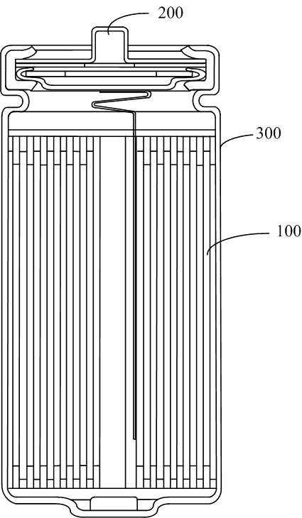
[0027] figure 1 It is a schematic structural diagram of a lithium-iron disulfide battery according to the first embodiment of the present invention, and the lithium-iron disulfide battery includes a battery cell 100 , a positive electrode upper cover assembly 200 and a battery case 300 .

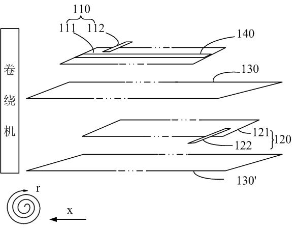
[0028] The battery cell 100 includes a positive electrode structure 110, a negative electrode structure 120, a first separator 130, a second separator 130' and an insulating tape 140.

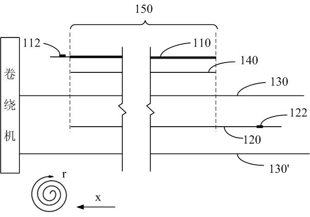
[0029] Wherein, the positive electrode structure 110 includes a rectangular positive electrode sheet 111 formed by coating a substrate with a mixture containing iron disulfide, and a positive electrode tab 112 connected to one end of the positive electrode sheet 111 .

[0030] The negative electrode structure 120 includes a r...

no. 2 approach

[0041] The following reference Figure 4 and Figure 5 , detailing the specific structure of the lithium-iron disulfide battery according to the second embodiment of the present invention.

[0042] The structure of the lithium-iron disulfide battery in the first embodiment is roughly the same, except that the position of the insulating band is different from the position of the insulating band in the first embodiment. The lithium-iron disulfide battery according to this embodiment also includes The battery cell 100 , the positive electrode upper cover assembly 200 and the battery case 300 .

[0043] The battery cell 100 includes a positive electrode structure 110, a negative electrode structure 120, a first separator 130, a second separator 130' and an insulating tape 140.

[0044] Wherein, the positive electrode structure 110 includes a rectangular positive electrode sheet 111 formed by coating a substrate with a mixture containing iron disulfide, and a positive electrode t...


PUM

PropertyMeasurementUnit
widthaaaaaaaaaa
widthaaaaaaaaaa
thicknessaaaaaaaaaa

Abstract

The invention relates to a Li-FeS2 battery comprising an anodal structure, a double-layered diaphragm, a cathodic structure, an anodal upper lid combined body and a battery case, wherein the anodal structure, the double-layered diaphragm, and the cathodic structure are stacked together to form a battery electrical core through rolling; an insulation belt is arranged between the anodal structure and the diaphragm, or between the cathodic structure and the diaphragm, and the insulation belt at least covers the overlapped part of the anodal structure and the cathodic structure; and the chemical reaction taken place at the part of the anodal structure or the cathodic structure covered by the insulation belt is later than the non-covered part, so that the covered cathodic structure can play a role of transferring electrons. By adopting the Li-FeS2 battery comprising an anodal structure, the problems that the active substances in the battery is not fully utilized and the battery voltage suddenly falls are solved, and the problems are caused by the reason that the cathodic structure fracture and the conductive base body loss in the non-reacted part of the cathodic structure because reaction is taken place earlier at the end of the cathodic structure far away from a negative tab.

Description

technical field [0001] The present invention relates to the field of primary lithium batteries, in particular, relates to the use of iron disulfide (FeS 2 ) as the positive electrode active material, lithium-iron disulfide (Li / FeS 2 )Battery. Background technique [0002] With the development of electronic technology and information technology, ordinary zinc-manganese batteries and alkaline manganese batteries can no longer meet the requirements of high-end electronic equipment. It is easy to produce concentration polarization, which will lead to an increase in the internal resistance of the battery, an increase in the internal consumption of the battery, and the battery will not be able to perform high-power discharge for a long time. Therefore, as a lithium battery with high energy density, it has developed more and more rapidly in recent years, especially a lithium-iron disulfide battery capable of continuous high-power discharge has been developed. Lithium-iron disulf...

Claims


Application Information

Patent Timeline
Patent Type & Authority Applications(China)
IPC IPC(8): H01M6/14H01M2/34H01M2/16H01M2/18
CPCY02E60/12
Inventor 张清顺林建兴常海涛赵洋
Owner FUJIAN NANPING NANFU BATTERY
Why Eureka
Try Eureka