Connection method of power battery pack and battery pack produced thereby
A power battery pack and connection method technology, which is applied in the connection of power battery packs and the field of power battery packs, can solve the problems of reduced mileage, complicated manufacturing process, and high cost, and achieves improved contact reliability, convenient arrangement and combination, and energy saving social cost effect
- Summary
- Abstract
- Description
- Claims
- Application Information
AI Technical Summary
Problems solved by technology
Method used
Image
Examples
Embodiment 1
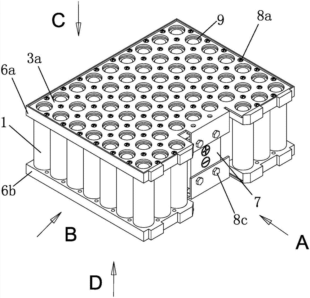
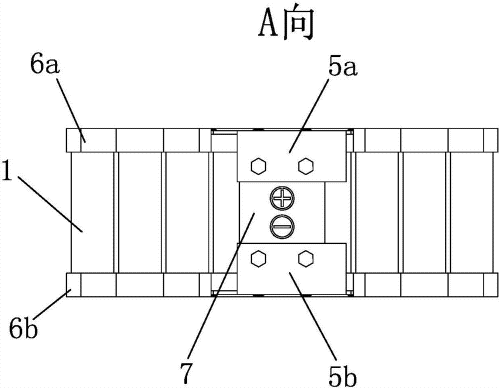
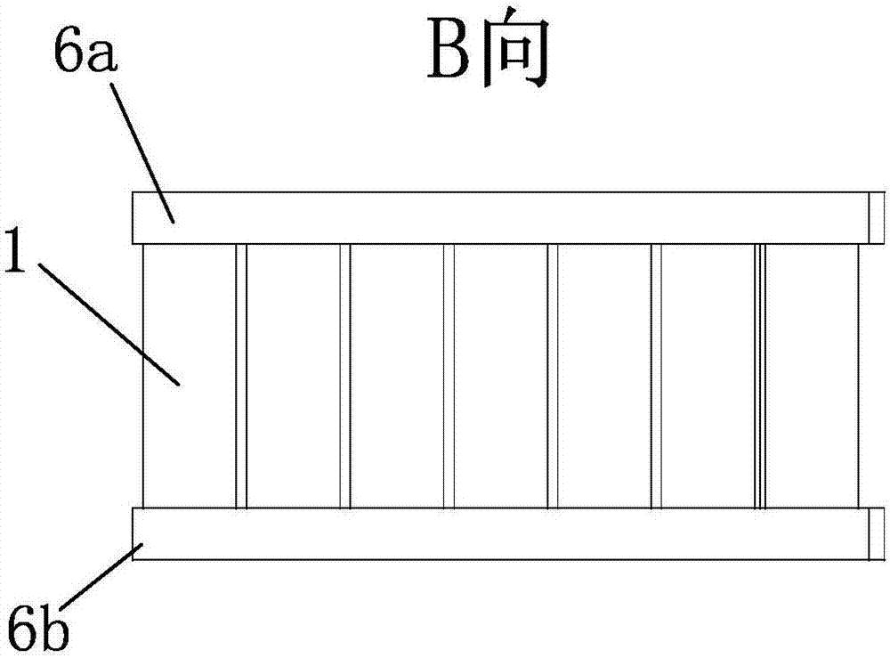
[0049] Such as Figure 1~6 As shown, a connection method of a power battery pack, the above-mentioned power battery pack includes several single cells 1, a manifold 3 and a battery bracket, the positive part of the above-mentioned single battery 1 is fixed by a 1# battery bracket 6a, and the above-mentioned single battery 1 The negative part is fixed by the 2# battery holder 6b.
[0050] Such as figure 1 , 6As shown, the above-mentioned manifold 3 is a copper-aluminum composite board, one side of the copper-aluminum composite board is a copper board, and the other side of the copper-aluminum composite board is an aluminum board. The face of the copper plate faces the electrode of the power battery pack, and the face of the aluminum plate faces away from the electrode of the power battery pack. Such as figure 1 , 4 , 5, and 6, specifically: the positive manifold 3a is a copper-aluminum composite plate, the copper plate of the positive manifold 3a faces the positive pole ...
Embodiment 2
[0059] Such as figure 1 , 3 , 4, as an improvement of the power battery pack connection method of the present invention, two-point welding is used between the single battery electrode and the fuse 2, and two-point welding is used between the aluminum plate surface and the fuse 2, Described welding step is as follows:
[0060] a. Weld a point between the fuse and the aluminum plate surface;
[0061] b. Pull the fuse to the battery terminal and weld a point between the fuse and the battery terminal;
[0062] c. Pull the fuse by 1 mm to 2 mm, and weld another point between the fuse and the battery electrode;
[0063] d. Pull the fuse to the aluminum plate and weld a point between the fuse and the aluminum plate;
[0064] e. Pull the fuse by 1mm to 2mm, and weld another point between the fuse and the aluminum plate surface;
[0065] f. Repeat steps b, c, d, and e until all the single cells in the same row are welded;
[0066] g. Pull the fuse to the aluminum panel, and weld...
Embodiment 3
[0072] The power battery pack includes several single cells 1, manifold 3 and battery holders, the positive part of the above-mentioned single cells 1 is fixed by the 1# battery holder 6a, and the negative part of the above-mentioned single cells 1 is fixed by the 2# battery holder 6b.
[0073] Such as figure 1 , 6 As shown, the above-mentioned manifold 3 is a copper-aluminum composite board, one side of the copper-aluminum composite board is a copper board, and the other side of the copper-aluminum composite board is an aluminum board. The face of the copper plate faces the electrode of the power battery pack, and the face of the aluminum plate faces away from the electrode of the power battery pack. Such as figure 1 , 4 , 5, and 6, specifically: the positive manifold 3a is a copper-aluminum composite plate, the copper plate of the positive manifold 3a faces the positive pole of the power battery pack, and the aluminum plate of the positive manifold 3a faces away from th...
PUM
| Property | Measurement | Unit |
|---|---|---|
| thickness | aaaaa | aaaaa |
Abstract
Description
Claims
Application Information
 - R&D
- Intellectual Property
- Life Sciences
- Materials
- Tech Scout
- Unparalleled Data Quality
- Higher Quality Content
- 60% Fewer Hallucinations
Browse by: Latest US Patents, China's latest patents, Technical Efficacy Thesaurus, Application Domain, Technology Topic, Popular Technical Reports.
© 2025 PatSnap. All rights reserved.Legal|Privacy policy|Modern Slavery Act Transparency Statement|Sitemap|About US| Contact US: help@patsnap.com


