

Press-fit type connector terminal
A connector terminal and matching technology, which is applied in the direction of connection, fixed connection, contact parts, etc., can solve the problems of printed circuit board electrical insulation degradation, circuit pattern resistance increase, printed circuit board whitening, etc., to reduce the number, Enhanced repeatable, stable contact effects
- Summary
- Abstract
- Description
- Claims
- Application Information
AI Technical Summary
Problems solved by technology
Method used
Image

Examples
no. 1 example )
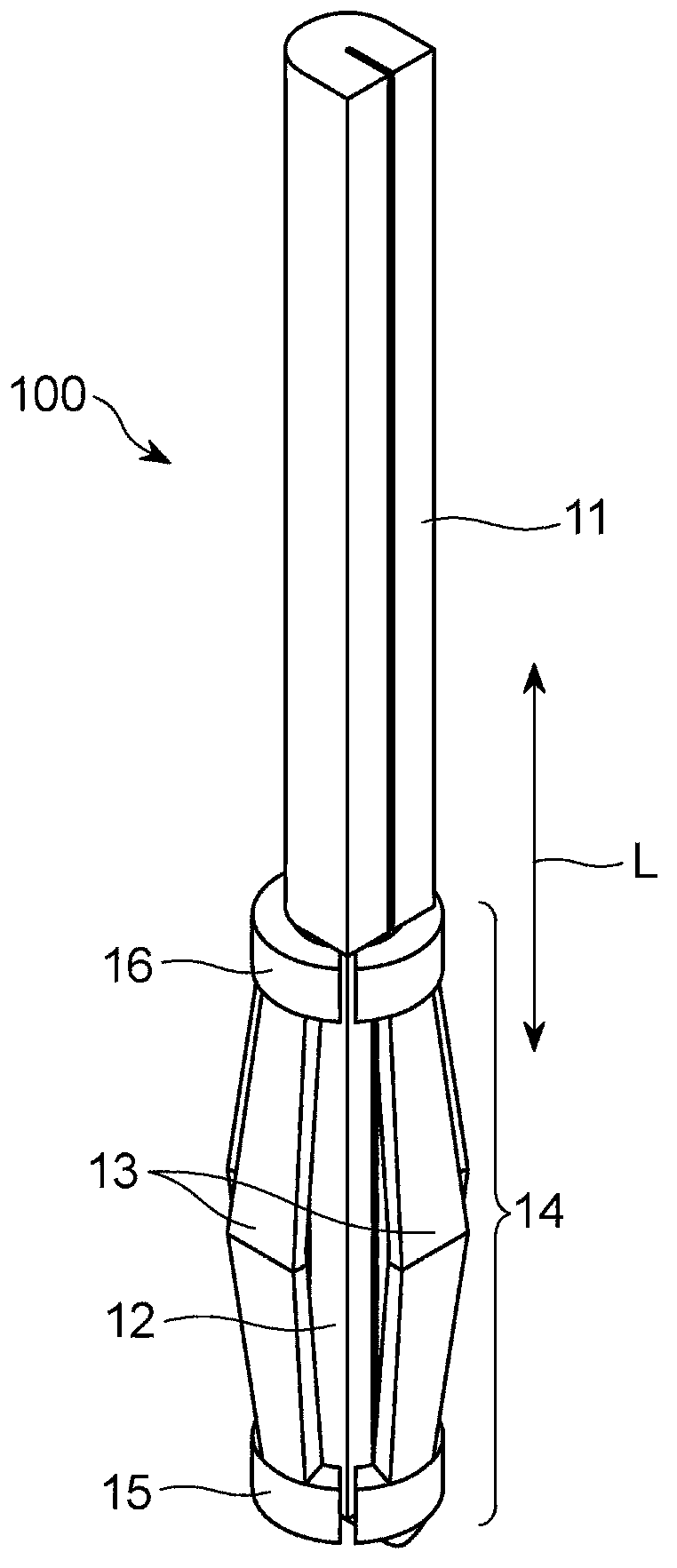
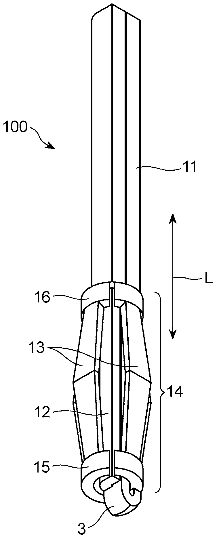
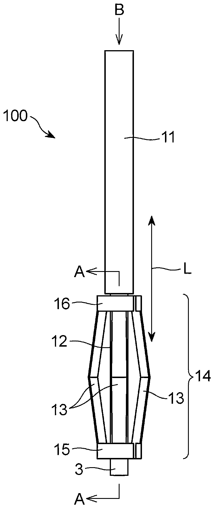
[0102] like Figures 1 to 8 shown in, by bending Figure 8 The single metal plate 8 having elasticity is shown to form the press-fit type connector terminal 100 according to the first embodiment of the present invention.
[0103] The press-fit type connector terminal 100 includes: a pin portion 11 having a U-shaped cross section; an inner shaft portion 12 continuous with the front end of the pin portion 11; and a contact portion 14 including a plurality of “<”-shaped contact pieces 13 , the contact pieces 13 extend parallel to the longitudinal axis of the inner shaft portion 12, protrude outward to surround the inner shaft portion 12, and are equidistantly spaced from adjacent contact pieces.
[0104] Each of the contact pieces 13 defining the contact portion 14 is formed at its distal and proximal ends with C-shaped binders 15 and 16 surrounding the inner shaft portion 12 .
[0105] like Figures 1 to 3 As shown, the press-fit type connector terminal 100 includes: an elong...
no. 2 example )
[0115] The following reference Figures 9 to 14 A press-fit type connector terminal 200 according to a second embodiment of the present invention is explained. by bending Figure 14 A resilient single metal plate 210 is shown to form the press-fit type connector terminal 200 .
[0116] The press-fit type connector terminal 200 includes: a pin portion 211 having a U-shaped cross section; an inner shaft portion 212 continuous with the front end of the pin portion 211; and a contact portion 214 including a plurality of “<”-shaped contact pieces 213 , the contact pieces 213 extend parallel to the longitudinal axis of the inner shaft portion 212 , protrude outward to surround the inner shaft portion 212 , and are equidistantly spaced from adjacent contact pieces 213 .
[0117] Each of the contact pieces 213 defining a contact portion 214 is formed at its distal and proximal ends with C-shaped binders 215 and 216 surrounding the inner shaft portion 212 . The prong portion 211 is ...
no. 3 example )
[0125] The following reference Figures 15 to 20 A press-fit type connector terminal 300 according to a third embodiment of the present invention will be described. by bending Figure 20 A resilient single metal plate 310 is shown to form the press-fit type connector terminal 300 .
[0126] The press-fit type connector terminal 300 includes: a pin portion 311 having a U-shaped cross section; an inner shaft portion 312 continuous with the front end of the pin portion 311; and a contact portion 314 including a plurality of “<”-shaped contact pieces 313 , the contact pieces 313 extend parallel to the longitudinal axis of the inner shaft portion 312 , protrude outward to surround the inner shaft portion 312 , and are equidistantly spaced from adjacent contact pieces 313 .
[0127] Each of the contact pieces 313 defining a contact portion 314 is formed at its distal and proximal ends with C-shaped binders 315 and 316 surrounding the inner shaft portion 312 . The pin portion 311 ...
PUM
 Abstract
Description
Claims
Application Information