Anode electric-conducting device used for aluminum electrolysis

A conductive device and aluminum electrolysis technology, applied in the field of conductive anode devices, can solve the problems of expanding the local cracking failure of the aluminum-steel welding surface, reducing the service life of the explosive welding block, etc.

Pending Publication Date: 2019-03-26
师建军
View PDF0 Cites 5 Cited by
  • Summary
  • Abstract
  • Description
  • Claims
  • Application Information

AI Technical Summary

Problems solved by technology

In the disclosed prior art, due to its specific structure, no matter the transition block structure of explosion welding or the steel-aluminum junction formed by friction welding bears the dual action of conducting electricity and carrying the gravity load of anode steel claws and carbon blocks at the same time, This effect will expand the failure of local cracking of the aluminum-steel welding surface and reduce the service life of the explosion welding block

Method used


Image

  • Anode electric-conducting device used for aluminum electrolysis
  • Anode electric-conducting device used for aluminum electrolysis
  • Anode electric-conducting device used for aluminum electrolysis

Examples


Embodiment 1

[0033] 1.1 Preparation method of the device

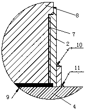
[0034] Take a cylindrical aluminum rod as a conductive guide rod, turn a section of external thread at one end of the guide rod, and make an undercut at the top of the external thread. Prepare a steel sleeve 2 with an internal thread that can cooperate with the aforementioned external thread, and screw the steel sleeve 2 on the threaded section of the guide rod. Make pattern at the corresponding position on the upper surface of steel claw crossbeam 4 in advance, and the most convenient way is to turn and go out annular pattern. The beam 4 is welded to the full cross-section of the steel claw head 5, for example, by friction welding. After the steel claw is prepared, the guide rod is combined with the upper surface of the steel claw beam 4 by friction welding, and the aluminum released during friction welding is filled in the steel sleeve 2 Between the lower end surface and the upper surface of the steel claw beam 4. Put the trans...

Embodiment 2

[0038] 2.1 Preparation method of the device

[0039] The preparation method of this embodiment is basically the same as that of Example 1, the difference is that this embodiment does not set an excessive steel sleeve, but after the guide rod and the upper surface of the steel claw beam 4 are friction welded together, the lower part of the steel sleeve 2 is directly Ring welding is carried out between the outer wall and the upper surface of the steel claw beam 4 and fixed.

[0040] 2.2 Structure of the device

[0041] The structure of the embodiment is basically with the attached figure 1 , but it is not provided with an excessive steel sleeve 3.

[0042] The above two embodiments are applicable to newly prepared conductive devices, and it can be known from the above description that the guide rod of the present invention is an integral component.

Embodiment 3

[0044] 3.1 Preparation method of the device

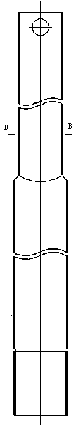
[0045] The guide bar of the old conductive device after service failure is sawed off to be the upper guide bar 1 for use, and the upper guide bar 1 is a square section. Take a section of cylindrical aluminum rod as the conductive lower guide rod 8, turn a section of external thread at the lower end of the lower guide rod 8, and make an undercut at the top of the external thread. Prepare a steel sleeve 2 with an internal thread that can cooperate with the aforementioned external thread, and screw the steel sleeve 2 on the threaded section of the guide rod. Make pattern at the corresponding position on the upper surface of steel claw crossbeam 4 in advance, and the most convenient way is to turn and go out annular pattern. The beam 4 is welded to the full section of the steel claw head 5, and after the steel claw is prepared, the guide rod and the upper surface of the steel claw beam 4 are friction welded together, and the aluminum ...


PUM


Abstract

The invention discloses an electric-conducting anode device used in aluminum electrolysis. A guide rod in the electric-conducting device is composed of an upper guide rod body and a lower guide rod body. The section of the upper guide rod body is at least provided with two parallel sides, and the section of the lower guide rod body is circular, an external thread is arranged on the portion, abovethe lower end surface of the lower guide rod body, of the lower guide rod body, the external thread segment of the lower guide rod body is connected with a steel sleeve provided with an internal thread, the lower end surface of the lower guide rod body is combined with the upper surface of a steel claw cross beam in a friction welding mode, and the steel claw cross beam is in welding combination with the steel sleeve. By means of the electric-conducting anode device provided by the invention, shortcomings in the prior art are overcome, the service life of the device is more than two times thatof a device made through a traditional technology, and existing resources can be fully utilized.

Description

technical field [0001] The invention relates to a conductive anode device used in aluminum electrolysis. The device includes an aluminum guide rod and an anode steel claw connected with the guide rod. Background technique [0002] The anode conductive device currently used in the electrolytic aluminum industry consists of an upper aluminum guide rod and a lower steel anode steel claw. The steel and aluminum cannot be directly welded, and the two are connected by an explosive welding block. Explosive welding nuggets are welded together by using explosive welding technology to weld two different materials, steel and aluminum. When making the anode conductive device, the aluminum part of the explosive welding nugget is welded with the upper aluminum guide rod part of the anode conductive device through argon arc welding, and the explosive The steel part of the welding block is welded to the flat steel of the lower anode steel claw beam of the anode conductive device through gas...

Claims


Application Information

Patent Timeline
Patent Type & Authority Applications(China)
IPC IPC(8): C25C3/12
CPCC25C3/12
Inventor 师建军
Owner 师建军
Why Eureka
Try Eureka