A service life testing method for metal joint bearings in fixed hinges of low-floor vehicles

A technology of joint bearing and low-floor car, which is applied in the direction of mechanical bearing testing, measuring devices, instruments, etc., can solve the problems of complex structure of metal joint bearing, difficult disassembly and assembly, and low detection efficiency.

Active Publication Date: 2019-07-26
ZHUZHOU TIMES NEW MATERIALS TECH
View PDF10 Cites 0 Cited by
  • Summary
  • Abstract
  • Description
  • Claims
  • Application Information

AI Technical Summary

Problems solved by technology

[0009] None of the above-mentioned patent documents discloses the service life detection method of the metal joint bearing of the fixed hinge, and the metal joint bearing of the fixed hinge is all matched with the center pin to connect the adjacent vehicle body, therefore, the structure of the metal joint bearing is relatively complicated, and it is difficult to dismantle it. Difficult to install, low detection efficiency

Method used


Image

  • A service life testing method for metal joint bearings in fixed hinges of low-floor vehicles
  • A service life testing method for metal joint bearings in fixed hinges of low-floor vehicles
  • A service life testing method for metal joint bearings in fixed hinges of low-floor vehicles

Examples


Embodiment 1

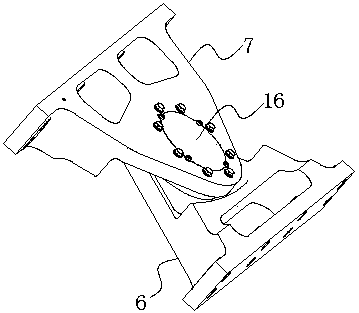
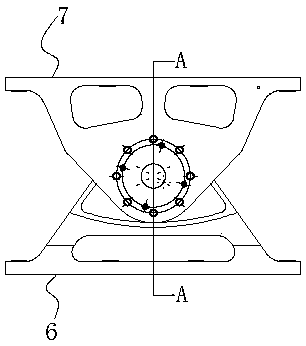
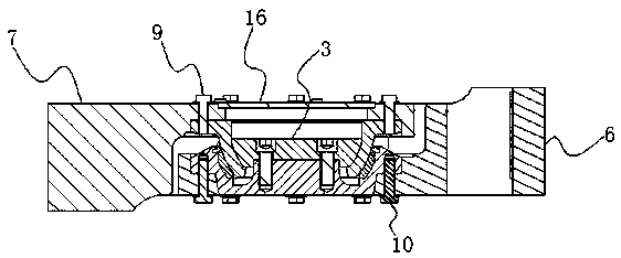
[0054] Embodiment 1: as Figure 1 to Figure 4 As shown, a method for detecting the service life of the metal joint bearing in the fixed hinge of the low-floor vehicle, the metal joint bearing in the fixed hinge of the low-floor vehicle is set as the outer seat cover 1 of the metal joint, the outer rolling ball sleeve 2 and the inner rolling ball 3 three set the outer rolling ball sleeve 2 inside the metal joint outer seat cover 1, the inner rolling ball 3 is arranged inside the outer rolling ball sleeve 2, and between the metal joint outer seat cover 1 and the outer rolling ball sleeve 2. A wear-resistant bushing 4 is provided; between the inner rolling ball 3 and the outer rolling ball sleeve 2 and between the outer rolling ball sleeve 2 and the wear-resistant bushing 4 are all in contact with the spherical surface, and the outer seat of the metal joint is fixed by the screw 5 Sleeve 1, outer rolling ball sleeve 2, inner rolling ball 3 and wear-resistant bush-4 form an integr...

Embodiment 2

[0071] Embodiment 2: as Figure 9 As shown, there is a gap between the other end surface P3 of the axial extension part 212 of the outer rolling ball sleeve and the inner bottom surface P4 of the closed end of the metal joint outer seat sleeve 1. Preferably, the axial extension of the outer rolling ball sleeve The other end surface P3 of the outlet part 212 is set as a plane. Compared with the embodiment 1, the difference of this embodiment is that a distance measuring device 17 is arranged on the inner bottom surface P4 of the closed end of the metal joint outer seat cover 1. The distance-measuring device-17 can use devices such as a rangefinder or a distance sensor. The distance-measuring device-17 is used to measure the position of the other end face P3 of the axial extension of the outer rolling ball sleeve, that is, to measure the axis of the outer rolling ball sleeve. The vertical distance between the other end face P3 of the protruding part and the distance measuring de...

Embodiment 3

[0078] Embodiment 3: A flange 113 is provided on the outer peripheral surface of the sleeve body 111 of the metal joint outer seat sleeve and is located at one end of the sleeve body opening, and a threaded hole 8 is opened on the flange 113, and the base 211 of the outer rolling ball sleeve is also provided. There is a threaded hole 8; threaded into the threaded hole 8 on the base 211 of the outer rolling ball sleeve through the upper fixed support 7 through the connecting screw one 9 and screwed into the lower fixed support 6 through the connecting screw two 10 In the threaded hole 8 on the flange 113 of the metal joint outer seat cover body, thereby the integral metal joint bearing is arranged between the upper fixed support and the lower fixed support, as Figure 10 to Figure 12 As shown, compared with Embodiment 1, this embodiment differs in that: a horizontal detection through hole 18 is provided on the lower fixed support 6, and a horizontal detection hole is provided on...


PUM


Abstract

The invention discloses a method for detecting the service life of a metal knuckle bearing in a fixing hinge of a low-floor tramcar, and the method comprises the steps: setting the metal knuckle bearing in the fixing hinge of the low-floor tramcar into three parts: a metal knuckle external seat sleeve, an external rolling ball sleeve, and an internal rolling ball; setting the external rolling ball sleeve in the metal knuckle external seat sleeve, setting the internal rolling ball in the external rolling ball sleeve, and setting a first wear-resistant lining between the metal knuckle external seat sleeve and the external rolling ball sleeve; making the spherical contact between the internal rolling ball and the external rolling ball sleeve and between the external rolling ball sleeve and the first wear-resistant lining, and combining the metal knuckle external seat sleeve, the external rolling ball sleeve, the internal rolling ball and the first wear-resistant lining to form an integrated metal knuckle bearing through screws; and detecting the service life of the integrated metal knuckle bearing through detecting the wear degree of the first wear-resistant lining. According to the invention, the method can achieve the accurate detection of the service life of the metal knuckle bearing in the fixing hinge of the low-floor tramcar, reduces the maintenance cost, and guarantees the use performance and safety performance.

Description

technical field [0001] The invention relates to a method for detecting the service life of a metal joint bearing, in particular to a method for detecting the service life of a metal joint bearing in a fixed hinge of a low-floor vehicle. Background technique [0002] Low-floor vehicle Light rail vehicle, hereinafter referred to as low-floor vehicle, is a new type of transportation equipment in modern cities. Generally, there are 3, 5, and 7 vehicles in groups, which are connected by hinged system devices. The distance between the vehicle and the track surface is less than 40 cm. The car body hinge device is an important part of the car body connection of urban low-floor vehicles. At present, with the wide application of low-floor vehicles in Europe, it is also being promoted in China, so the market demand for hinge devices is also increasing. [0003] The hinged device of the car body is arranged at the connecting part of the two ends of the car body, and the upper and lower ...

Claims


Application Information

Patent Timeline
Patent Type & Authority Patents(China)
IPC IPC(8): G01M13/04G01B21/02
CPCG01B21/02G01M13/04
Inventor 罗斌刘文松庄征宇杜方孟邹敏佳罗燕荣继刚
Owner ZHUZHOU TIMES NEW MATERIALS TECH
Why Eureka
Try Eureka