

Wear resistance detecting device for automobile accessories
A detection device and auto parts technology, applied in the detection field, can solve the problems of expensive equipment, complicated operation, inability to adjust the pressure of friction mechanism and parts in time, etc., and achieve the effect of novel design
- Summary
- Abstract
- Description
- Claims
- Application Information
AI Technical Summary
Problems solved by technology
Method used
Image

Examples
Embodiment Construction
[0017] The following will clearly and completely describe the technical solutions in the embodiments of the present invention with reference to the accompanying drawings in the embodiments of the present invention. Obviously, the described embodiments are only some, not all, embodiments of the present invention.
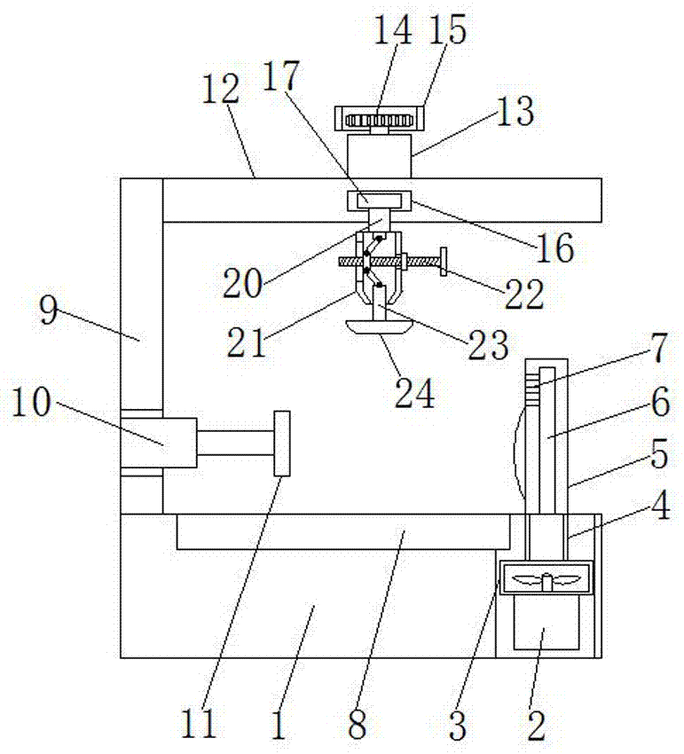
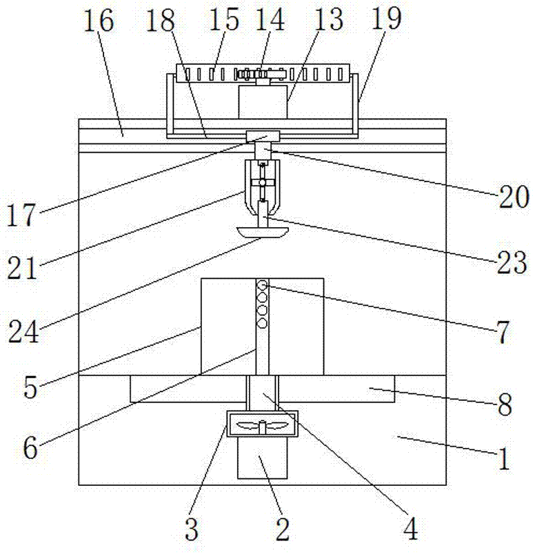
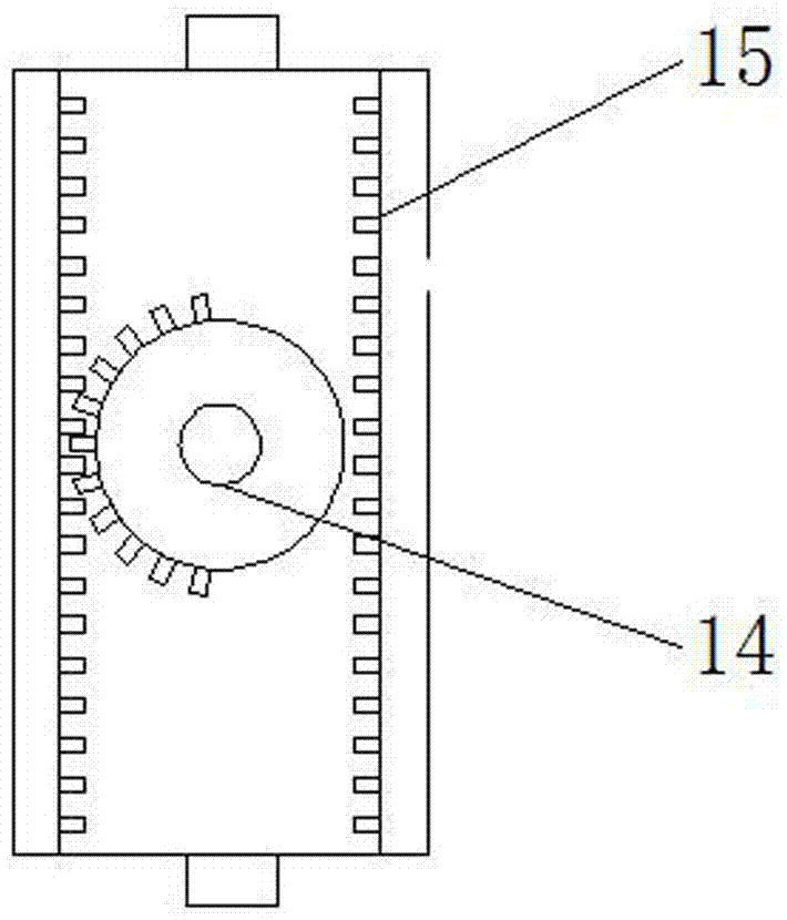
[0018] refer to Figure 1-3 , a wear-resistant detection device for auto parts, including a base 1, a groove is opened inside one side of the base 1, a first drive motor 2 is installed in the groove, and a bellows 3 is sleeved on the output shaft of the first drive motor 2, The top outer wall of the bellows 3 is welded with an air duct 4, and the end of the air duct 4 away from the bellows 3 is equipped with a baffle 5 welded vertically to the base 1, and the inside of the baffle 5 is provided with a ventilation duct 6 along its height direction, and the ventilation duct 6 It communicates with the air duct 4, and one side of the baffle 5 is provided with a plurality ...
PUM
 Abstract
Description
Claims
Application Information