
High-speed closed switch

A closed switch, high-speed technology, applied in electrical switches, power devices inside switches, electrical components, etc., can solve problems such as poor contact, low switch closing speed, arc oxidation, etc. The effect of a small risk of electric shock

Active Publication Date: 2017-12-12
滨州市科创孵化器有限公司
View PDF6 Cites 0 Cited by
  • Summary
  • Abstract
  • Description
  • Claims
  • Application Information

AI Technical Summary

Problems solved by technology

[0002] With the development of society, electricity has penetrated into all aspects of production and life. The control of electricity usually requires a variety of switches. The current commonly used knife switch usually needs to be manually pushed up the handle to close the switch. This switch closing speed Low, the arc generated during the closing process will oxidize the switch contacts, resulting in poor contact. At the same time, when the operator closes the switch, he is very close to the dynamic and static contacts, which is prone to electric shock accidents. operating switch

Method used


Image

  • High-speed closed switch
  • High-speed closed switch
  • High-speed closed switch

Examples


Embodiment

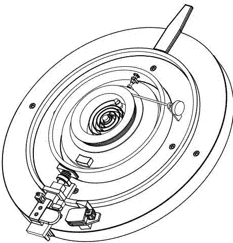
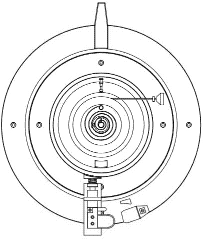
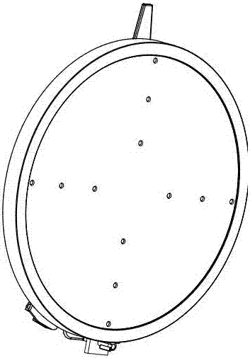
[0028] like figure 1 , figure 2 , image 3 , Figure 4 , Figure 5 , Image 6 , Figure 7 , Figure 8 , Figure 9 , Figure 10 , Figure 11 , Figure 12 , Figure 13 , Figure 14 As shown, a high-speed closing switch includes an end cover 1, a rotating mechanism 2, a moving contact assembly 3, a transmission ring 4, a first fixing assembly 5, a second fixing assembly 6, a third fixing assembly 7, a driving module 8, The coil spring 9 is characterized in that: the first fixing assembly 5 is fixedly installed on the end cover 1, and the slip ring 201 at the bottom of the rotating mechanism 2 is rotatably installed in the first circular groove on the rear end surface of the first circular seat 501 507, the moving contact assembly 3 is installed on the rotating mechanism 2; the second fixing assembly 6 is fixedly installed on the end cover 1, and the transmission ring 4 is installed on the rear end surface of the second ring seat 601 by rotating the flange at the bott...


PUM


Abstract

A high-speed closed switch comprises an end cap, a rotating mechanism, a movable contact component, a transmission ring, a first fixing component, a second fixing component, a third fixing component, a driving module and a coil spring, and is characterized in that the first fixing component is fixedly mounted on the end cap, the sliding ring at the bottom of the rotating mechanism is rotatably mounted in the first annular groove in the rear end surface of a first annular seat, the movable contact component is mounted on the rotating mechanism, the second fixing component is fixedly mounted on the end cap, and the transmission ring is rotatably mounted in a second annular groove in the rear end surface of a second annular seat through a flange at the bottom. For the switch, a manual pulling rope is adopted as the coil spring for storing energy, the coil spring drives the driving module to drive the rotating mechanism to rotate under centrifugal force so as to close the switch, an operator can pull the rope out to keep away from the switch, so that the risk of electric shock for the operator is reduced; moreover, the switch closes fast thus being safe and efficient.

Description

technical field [0001] The invention relates to the technical field of power switches, in particular to a high-speed closing switch. Background technique [0002] With the development of society, electricity has penetrated into all aspects of production and life. The control of electricity usually requires a variety of switches. The current commonly used knife switch usually needs to be manually pushed up the handle to close the switch. This kind of switch closing speed Low, the arc generated during the closing process will oxidize the switch contacts, resulting in poor contact. At the same time, when the operator closes the switch, he is very close to the dynamic and static contacts, which is prone to electric shock accidents. Operate the switch. Contents of the invention [0003] Aiming at the above problems, the present invention provides a high-speed closing switch. The present invention uses a manual pull rope to store energy for the coil spring. The coil spring driv...

Claims


Application Information

Patent Timeline
IPC IPC(8): H01H3/30H01H17/08
CPCH01H3/30H01H3/3005H01H17/08
Inventor 韩朝锋
Owner 滨州市科创孵化器有限公司
Learn More