Artificial hip replacement device
A hip joint prosthesis and artificial technology, applied in the direction of hip joints, joint implants, joint implants, etc., can solve the problems of shortening the service life of artificial hip joint prosthesis, artificial hip joint loosening, adverse biological reactions, etc. , to avoid the risk of secondary surgery, reduce surgical trauma, and high wear resistance
- Summary
- Abstract
- Description
- Claims
- Application Information
AI Technical Summary
Problems solved by technology
Method used
Image
Examples
Embodiment 1
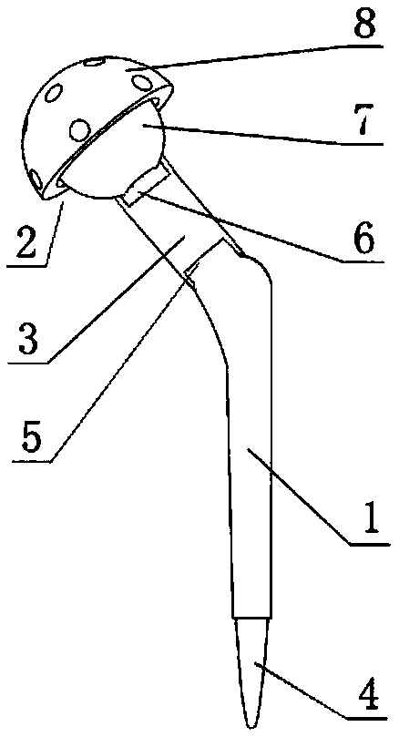
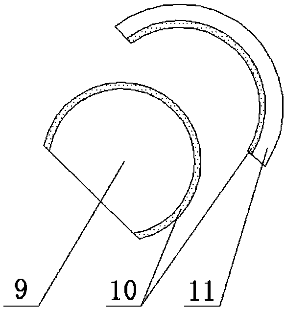
[0025] Such as figure 1 As shown, the artificial hip joint prosthesis includes a femoral stem 1, a femoral ball head 2, and an elastic connector 3. The distal end 4 of the femoral stem 1 can be inserted into the femoral medullary cavity, and the proximal end 5 of the femoral stem extends laterally and upwardly. In the natural state, the angle between the axis of the extension end and the axis of the femoral stem is 110°-140°, and the end of the extension end suddenly becomes thinner into a step shape, and the thin section extends 6-10 mm upward to the side for fixing the elastic connector 3, One end of the elastic connector 3 is inserted into the thin section and leans against the step, the other end of the elastic connector 3 is connected to the femoral ball head 2, and the connection between the femoral ball head and the elastic connector 3 has a columnar protrusion 6 with a length of 6-10 mm. The columnar protrusion 6 realizes the fixed connection between the elastic connec...
Embodiment 2
[0032] Such as figure 1 As shown, most of the structure of the artificial hip joint prosthesis of the present invention is the same as that of Embodiment 1, the difference is that the elastic connector 3 in this embodiment is a cylindrical elastic metal, and its hollow structure can save materials and ensure Sufficient elasticity is required, and it is fixedly connected with the femoral stem 1 and the femoral ball head 2 at both ends respectively through interference fit. In addition, the elastic connector 3 can also be equipped with a locking mechanism, and 2-3 inward protrusions are provided near the end, and 2-3 inward protrusions are provided at the corresponding connecting positions of the femoral stem 1 and the femoral ball head 2 . The groove is used to lock with the protrusion on the elastic connector 3. The elastic connecting member 3 can also be fixedly connected by clamping, welding and other connection methods.
Embodiment 3
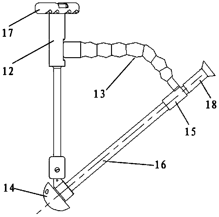
[0034] The present invention also provides a replacement device for implanting the aforementioned artificial hip joint prosthesis into the human body, such as image 3 As shown, the replacement device has a joystick 12, a guiding telescopic rod 13, an acetabular cup connector 14, a sleeve 15 and an acetabular cup knocking rod 16, the proximal end of the joystick 12 has a fixedly connected handle 17, and the distal end The acetabular cup connector 14 is connected, and a guiding telescopic rod 13 is fixedly connected under the handle. The other end of the guiding telescopic rod is provided with a sleeve 15. The sleeve is used to insert the acetabular cup knocking rod 16. The guiding telescopic rod 13 has a certain Elasticity and support, can be bent, stretched and shortened in all directions, so as to adjust the distance between the sleeve 15 and the acetabular cup connector 14 as needed, and align the two to facilitate installation, which must be adjusted in advance Guide the d...
PUM
| Property | Measurement | Unit |
|---|---|---|
| verticality | aaaaa | aaaaa |
| thickness | aaaaa | aaaaa |
Abstract
Description
Claims
Application Information
 - R&D
- Intellectual Property
- Life Sciences
- Materials
- Tech Scout
- Unparalleled Data Quality
- Higher Quality Content
- 60% Fewer Hallucinations
Browse by: Latest US Patents, China's latest patents, Technical Efficacy Thesaurus, Application Domain, Technology Topic, Popular Technical Reports.
© 2025 PatSnap. All rights reserved.Legal|Privacy policy|Modern Slavery Act Transparency Statement|Sitemap|About US| Contact US: help@patsnap.com


