
Sealed damp-proof electric meter box

An electric meter box, sealed technology, applied in the measurement of electrical variables, measuring devices, instruments, etc., can solve the problems of electrical faults of smart meters, poor moisture-proof and moisture-proof effects, and inability to ensure tightness, etc., to improve the waterproof effect, enhance the The effect of the waterproof effect

Pending Publication Date: 2017-12-15
国网河南省电力公司内乡县供电公司
View PDF7 Cites 7 Cited by
  • Summary
  • Abstract
  • Description
  • Claims
  • Application Information

AI Technical Summary

Benefits of technology

The present inventor's new type of watermark lockbox has three main parts: an enclosed case containing various components like a circuit board or battery module, a lid sheet attached inside this case, and two covers called top and back lids. These boxes have different designs based on their intended use but they each require certain features such as good water resistance without any holes left open during construction. To achieve these goals, the walls around them must meet specific requirements set up beforehand. Additionally, the boxes should maintain proper alignment when installed properly due to environmental factors like wind pressure. Overall, the innovation improves the overall performance and durability of the watermarks locked in the key locks used in meters.

Problems solved by technology

The technical problem addressed in this patented text relates to improving the functionality and performance of electric grids without compromising their environmental protection capabilities due to poor air quality conditions during winter months when they operate at low temperatures (-25°C). Current solutions involve adding expensive equipment within the electric grid itself, making them difficult to maintain properly.

Method used


Image

  • Sealed damp-proof electric meter box
  • Sealed damp-proof electric meter box
  • Sealed damp-proof electric meter box

Examples


Embodiment 1

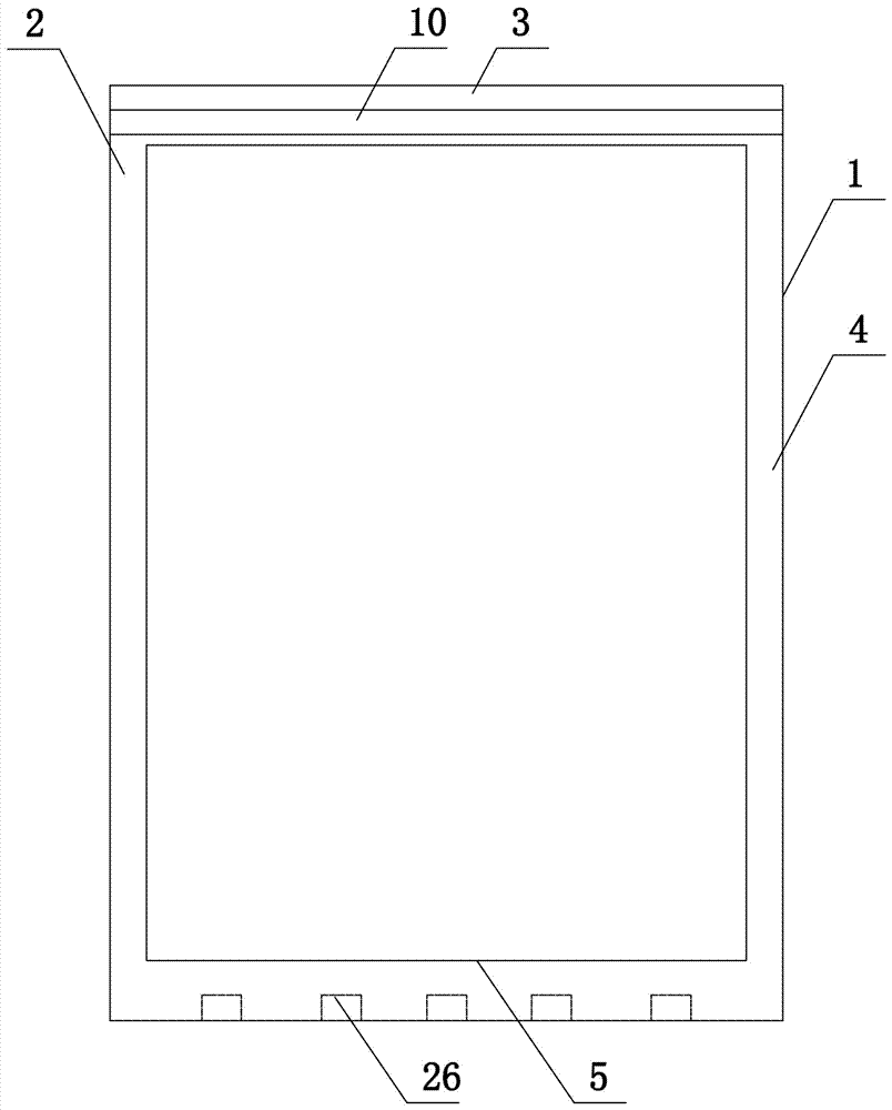
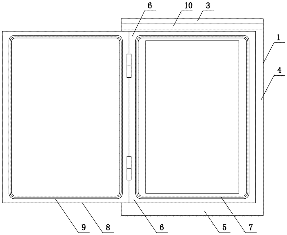
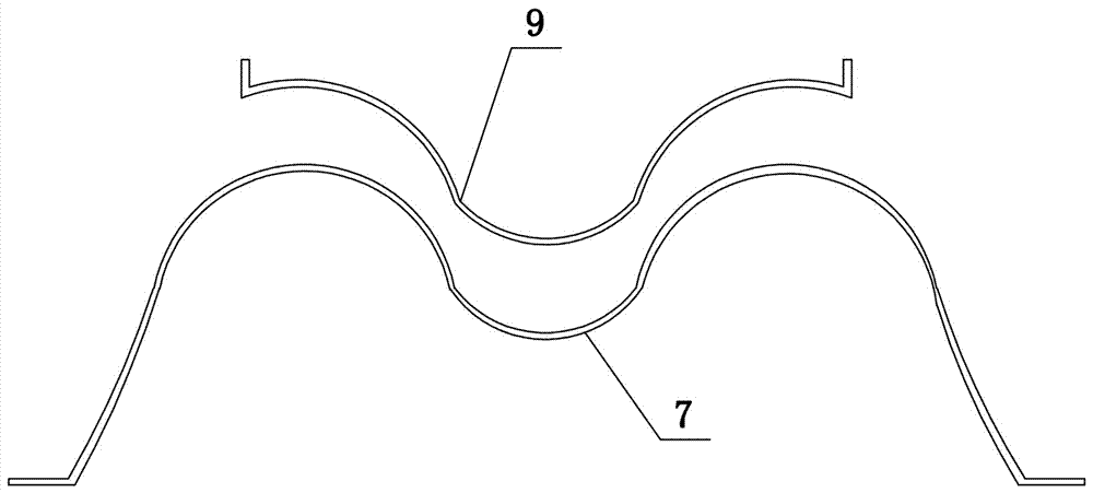
[0037] Such as Figure 1 to Figure 3 As shown, the present invention comprises box body 1, and box body 1 is integrally formed structure, and wherein the front baffle plate of box body 1 is rectangular frame structure, and front baffle plate comprises left plate body 2, upper plate body 3, right plate body connected end to end. Body 4 and lower plate body 5, the outer end faces of left plate body 2, upper plate body 3, right plate body 4 and lower plate body 5 are all provided with grooves 6, four grooves 6 are connected end to end, four grooves 6 inner The first rubber sealing strip 7 connected end to end is provided. The first rubber sealing strip 7 is a hollow structure and its front end surface is M-shaped. The cover plate 8 is hinged in the groove of the left plate body 2. The cover plate 8 is made of transparent plastic material. , the outer end face of the cover plate 8 is located on the same vertical plane as the outer end face of the front baffle, and the inner end fa...

Embodiment 2

[0040] The structure of this embodiment is basically the same as that of Embodiment 1, the difference is: as Figure 5 Shown, the outer end face of front baffle is provided with box door 17, and the inner end face of box door 17 is provided with thermal insulation layer 18, and thermal insulation layer 18 is the rock wool thermal insulation layer of 3-5mm.

Embodiment 3

[0042] The structure of this embodiment is basically the same as that of Embodiment 2, the difference is: as Figure 6 and Figure 7 As shown, the right end of the box door 17 is hinged with the left plate body 2, the left end of the box door 17 is provided with a plastic hook 19, the right plate body 4 is provided with a second accommodation cavity 20 and a hook accommodation hole 21, and the second accommodation cavity 20 Slidingly set the iron latch 22, the two ends of the iron latch 22 are respectively provided with a first electromagnet 23 and a second electromagnet 24, the coil winding direction of the first electromagnet 23 is opposite to the coil winding direction of the second electromagnet 24 , the single-chip microcomputer 25 is set in the casing, and the single-chip microcomputer 24 independently controls the energization and power-off of the two electromagnets.


PUM


Abstract

The invention belongs to the technical field of electrical equipment, and particularly relates to a sealed damp-proof electric meter box. The sealed damp-proof electric meter box comprises a box body. A front baffle of the box body comprises a left plate body, an upper plate body, a right plate body and a lower plate body which are connected end to end, the outer end faces of the left plate body, the upper plate body, the right plate body and the lower plate body are each provided with a groove, the four grooves are internally provided with first rubber sealing strips connected end to end, the first rubber sealing strips are of a hollow structure, and the front end faces of the first rubber sealing strips are in an M shape; a cover plate is hinged to the interior of the groove in the left plate, the outer end face of the cover plate and the outer end face of the front baffle are located on the same vertical face, the inner end face of the cover plate is provided with a second sealing rubber sealing strip connected with the first rubber sealing strips in a contact mode, the outer end face of the second rubber sealing strip is matched with the front end faces of the first rubber sealing strips, and the right end of the cover plate is fixedly connected with the groove in the right plate body. The cover plate and the box body are combined into a full-sealed structure, and the problem that water mist and tidal air enter the box body is solved fundamentally.

Description


Claims


Application Information

Patent Timeline
Owner 国网河南省电力公司内乡县供电公司
Features
  • Generate Ideas
  • Intellectual Property
  • Life Sciences
  • Materials
  • Tech Scout
  • Unparalleled Data Quality
  • Higher Quality Content
  • 60% Fewer Hallucinations
Learn More