
Bendable LED (light emitting diode) module, circular LED module and wavy LED module

An LED module, wave-shaped technology, applied in the field of display equipment, can solve the problems of high production cost, poor applicability, heavy weight, etc., and achieve the effects of reduced production cost, good display effect, and reduced weight

Active Publication Date: 2015-02-04
GLUX VISUAL EFFECTS TECH (SHENZHEN) CO LTD
View PDF9 Cites 8 Cited by
  • Summary
  • Abstract
  • Description
  • Claims
  • Application Information

AI Technical Summary

Problems solved by technology

[0004] The first technical problem to be solved by the present invention is the technical problem that the display effect of the existing bendable LED module is poor, so as to provide a bendable LED module with better display effect
[0005] The second technical problem to be solved by the present invention is that the existing bendable LED modules have discontinuous bending arcs and poor applicability, so as to provide a bendable LED module that can continuously adjust the bending arcs within a certain range and has strong applicability. Curved LED Module
[0006] The third technical problem to be solved by the present invention is that the existing bendable LED module has relatively complex structure, heavy weight and high production cost, so as to provide a flexible LED module with simple structure, light weight and low production cost. The bendable LED module

Method used


Image

  • Bendable LED (light emitting diode) module, circular LED module and wavy LED module
  • Bendable LED (light emitting diode) module, circular LED module and wavy LED module
  • Bendable LED (light emitting diode) module, circular LED module and wavy LED module

Examples


Embodiment 1

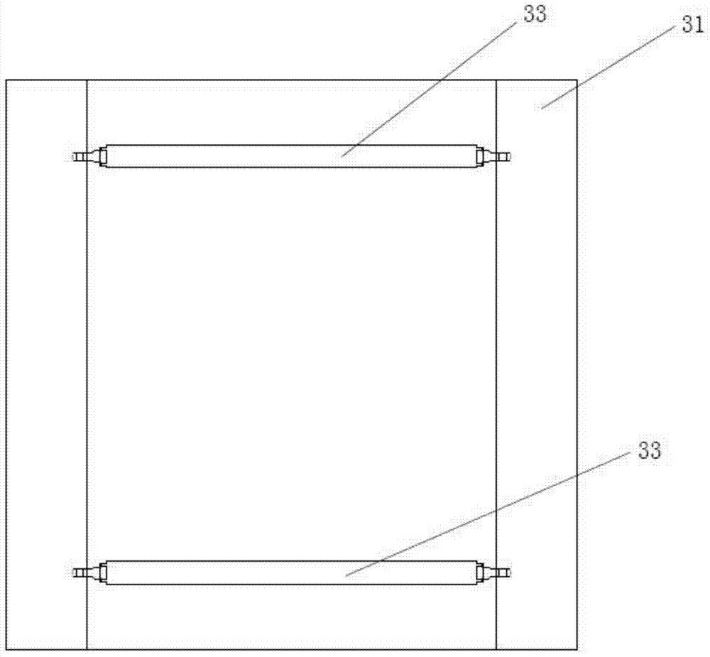
[0036] see Figure 1-4 , a bendable LED module, comprising: an elastic component layer 20 as an installation base, the elastic component layer 20 is installed with several light-emitting components, acting on the adjustment part 30 on the back of the elastic component layer 20, the adjustment part 30 The two sides of the elastic component layer 20 are supported or tensioned, so that the elastic component layer 20 is bent in an inner arc or an outer arc. The elastic component layer 20 is a material suitable for rebounding after bending deformation, so that the carbon fiber layer does not have large gaps or gaps between the light-emitting components after bending deformation, so that the display effect is better.

[0037] The bendable LED module of this embodiment has three usage states, wherein when the adjustment part 30 does not regulate the elastic member layer 20, the elastic member layer 20 is in the shape of a flat plate, which is suitable for transportation or storage; ...

Embodiment 2

[0046] This embodiment provides a circular LED module using the bendable LED module in Embodiment 1, see Figure 7 , the circular LED module is surrounded by a number of bendable LED modules with curved outer arcs, and the adjacent fixed blocks 31 of the adjacent bendable LED modules are screwed together, obviously the adjacent The connection method between the two fixing blocks 31 is not limited to screw connection, for example, bonding, riveting, inlaying and the like may also be used.

Embodiment 3

[0048] This embodiment provides a wave-shaped LED module using the bendable LED module in Embodiment 1, see Figure 8 , the wave-shaped LED module is composed of one / several bendable LED modules with curved inner arcs and one / several bendable LED modules with curved outer arcs, and the adjacent bendable LED modules The adjacent fixing blocks 31 of the module are screwed, obviously, the connection method between two adjacent fixing blocks 31 is not limited to screw connection, for example, bonding, riveting, inlaying, etc. can also be used.


PUM


Abstract

The invention discloses a bendable LED (light emitting diode) module, which comprises an elastic part layer (20) and an adjusting part (30), wherein a plurality of light emitting assemblies are arranged on the elastic part layer (20), the adjusting part (30) is arranged at the back part of the elastic part layer (20), and is tensioned or supported at the two sides of the elastic part layer (20), and the elastic part layer (20) is bent in an inner arc or outer arc way. The bendable LED module has the advantage that after the elastic part layer (20) is bent and deformed, a larger clearance or gap between the light emitting assemblies is avoided, so the display effect is better.

Description

technical field [0001] The invention relates to a bendable LED module, a circular LED module and a wave-shaped LED module, and relates to the technical field of display equipment. Background technique [0002] As an outdoor display device, the LED module is generally installed on the wall or bracket in the form of a flat panel to play advertisements or other images; in order to adapt to different installation environments and obtain better visual effects, people set the LED module in surface form. For example, Chinese patent CN202549189U discloses an S-shaped LED module. By setting a flexible connecting plate at the bend to connect the LED modules on both sides, the LED module in this patent document can be installed on a wall with corners. The S-shaped LED module has the following defects. 1. The S-shaped corner uses a U-shaped or V-shaped connecting plate to connect the LED modules on both sides. The LED module itself cannot be bent, so it is not suitable for abutting the...

Claims


Application Information

Patent Timeline
Patent Type & Authority Applications(China)
IPC IPC(8): G09F9/33
CPCG09F9/33G09F9/3026F21S4/22F21Y2115/10F21S2/005F21V17/02F21V17/12F21V19/003F21V19/02
Inventor 兰侠兰明徐元才
Owner GLUX VISUAL EFFECTS TECH (SHENZHEN) CO LTD
Learn More