Dustproof structure used for head-mounted display

A technology of dust-proof structure and display, applied to instruments, optical components, optics, etc., can solve the problems of inability to precisely adjust the distance of the lens holder, limited sliding range of the lens holder, affecting the user experience, etc., to achieve a simplified space layout, Easy to promote and use, elegant appearance

Active Publication Date: 2017-12-15
INLIFE HANDNET CO LTD
View PDF4 Cites 4 Cited by
  • Summary
  • Abstract
  • Description
  • Claims
  • Application Information

AI Technical Summary

Problems solved by technology

[0003] In the Chinese patent application with the application number 201510204170.6, the dust-proof solution for the head-mounted display adopted is to install the mounting part of the lens bracket on the mounting seat of the display bracket, and then place the ring-shaped soft rubber sleeve on the lens bracket The mounting part and the mounting seat of the display stand, although this solution has a certain dust-proof effect, but limited by the size of the mounting seat, the sliding range of the lens support is limited, resulting in a small adjustment range of the pupil distance. And by manually pushing the lens holders to adjust the interpupillary distance, it is impossible to accurately adjust the distance between the two lens holders, which affects the user experience of the user; in addition, this solution has the disadvantages of complex structure and high manufacturing cost.

Method used


Image

  • Dustproof structure used for head-mounted display
  • Dustproof structure used for head-mounted display
  • Dustproof structure used for head-mounted display

Examples


Embodiment Construction

[0025] In order to make the objectives, technical solutions, and advantages of the present invention clearer, the following further describes the present invention in detail with reference to the accompanying drawings and embodiments. It should be understood that the specific embodiments described here are only used to explain the present invention, but not to limit the present invention.

[0026] Unless otherwise defined, the technical terms or scientific terms used herein shall be the ordinary meanings understood by those with ordinary skills in the field to which the present invention belongs. The "first", "second" and similar words used in the specification and claims of the patent application of the present invention do not denote any order, quantity or importance, but are only used to distinguish different components. Similarly, similar words such as "one" or "one" do not mean a quantity limit, but mean that there is at least one.

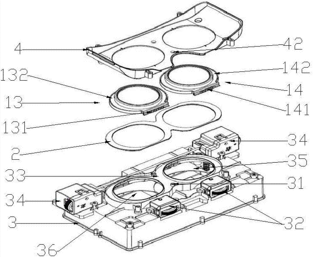
[0027] figure 1 It is a schematic diagram ...


PUM


Abstract

The invention relates to the field of head-mounted display equipment, and in particular, relates to a dustproof structure used for a head-mounted display. The dustproof structure comprises a display screen, a display screen bracket, a left lens, a right lens, a left lens frame, a right lens frame, a dustproof piece and an eye shield, wherein the display screen is fixed on the display screen bracket; a dustproof groove used for installing the dustproof piece is formed in the display screen bracket; the left lens is installed on the left lens frame, and the right lens is installed on the right lens frame; the left lens frame and the right lens frame are installed on the display screen bracket, and are in contact with the dustproof piece in the dustproof groove; and the eye shield is pressed on the left lens and the right lens, so that the left lens frame and the right lens frame are pressed on the dustproof piece with proper pressure. The dustproof structure provided by the invention makes full use of physical connection relationships among the components through reasonable design, simplifies the space layout, and has the advantages of simple structure and good dustproof effect.

Description

Technical field [0001] The present invention relates to the field of head-mounted display devices, and in particular, to a dust-proof structure for a head-mounted display. Background technique [0002] A head-mounted display is a device that magnifies the image on the ultra-micro display screen through a set of optical systems (mainly precision optical lenses), and projects the image on the retina, thereby presenting the large-screen image in the eyes of the viewer. With the progress and development of science and technology, head-mounted displays have gradually become civilians. The head-mounted displays currently on the market include: head-mounted displays that do not support pupil distance adjustment and head-mounted displays that support pupil distance adjustment. For head-mounted displays that support pupil distance adjustment, the In the limited mechanical design space of such products, it is necessary to design multiple solutions to improve the overall performance of the...

Claims


Application Information

Patent Timeline
Patent Type & Authority Applications(China)
IPC IPC(8): G02B27/01G02B27/00
CPCG02B27/0006G02B27/0176G02B27/01
Inventor 符大富李炜
Owner INLIFE HANDNET CO LTD
Why Eureka
Try Eureka