Rubber tire roller

一种橡胶轮胎、压路机的技术,应用在橡胶轮胎压路机领域,能够解决大施工空间、形成隧道复杂等问题

Active Publication Date: 2017-12-19
BOMAG
View PDF6 Cites 0 Cited by
  • Summary
  • Abstract
  • Description
  • Claims
  • Application Information

AI Technical Summary

Problems solved by technology

The disadvantage of this solution is that the tunneling inside the frame is relatively complicated, requires a lot of construction space, and only allows the driver a very limited view of the wheel edge or the wheel tread

Method used


Image

  • Rubber tire roller
  • Rubber tire roller
  • Rubber tire roller

Examples


Embodiment Construction

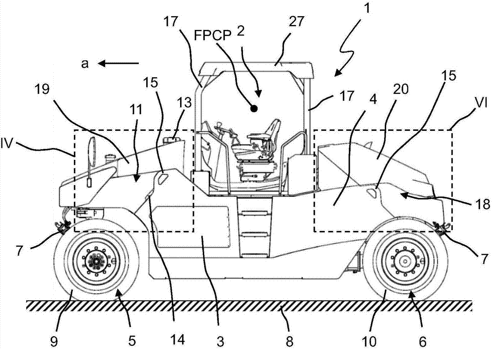
[0036] Components that are identical or have the same function are identified with the same reference numerals. Repeated components are not necessarily indicated individually in each figure.

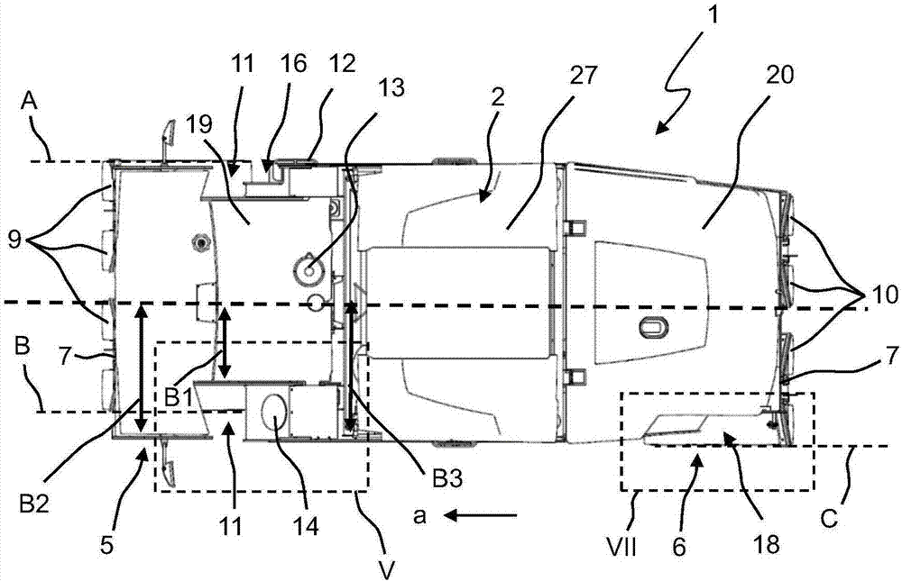
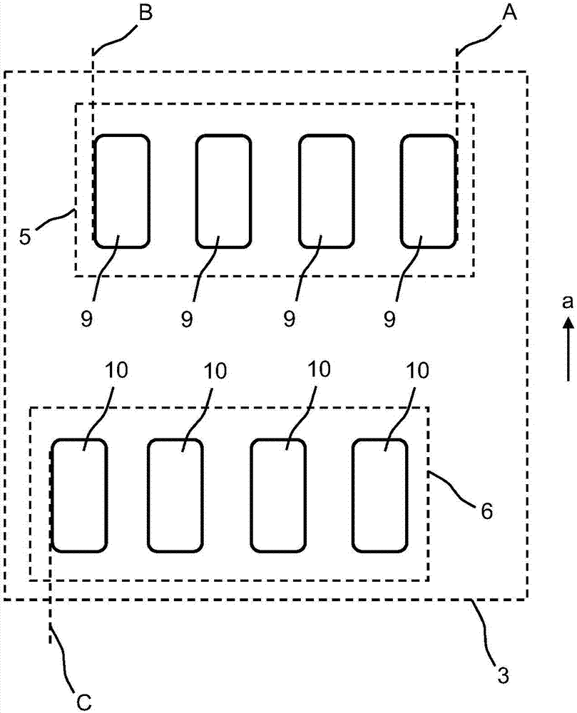
[0037] Figures 1 to 11 A preferred illustrative embodiment of a rubber-tyred road roller 1 according to the invention is shown. Generally, a rubber tire road roller 1 includes an operating platform 2 and a frame 3 . During operation, the rubber-tyred road roller 1 is driven by a power source 4, usually a diesel engine, and by means of a driven front chassis 5 and a rear chassis 6 over the ground 8 alternately in or against the direction of advancement a move. The chassis 5 and 6 each comprise four individual wheels arranged next to each other. Ideally, a driver's seat displaceable across the width of the platform is arranged on the console 2 . exist figure 1 In , the approximate position of the FPCP according to DINISO 5006:2017 is shown for illustrative purposes.

[0038] In ord...


PUM


Abstract

The present invention relates to a rubber tire roller for ground compaction, comprising a machine frame and an operating platform and front and rear undercarriages supporting the machine frame, wherein the undercarriages each comprise at least one wheel. A fundamental idea of the present invention lies in viewing indentations that are open to the side.

Description

technical field [0001] The invention relates to a rubber tire roller for ground compaction. Background technique [0002] Conventional rubber-tyred road rollers are known, for example, from EP 0 864 964 A2. Rubber-tyred rollers are ground compactors equipped with wheels (usually rubber) by which they are driven over the ground to be compacted. For this purpose, a common rubber tire road roller includes a frame with an operating platform and front and rear chassis supporting the frame, the front and rear chassis respectively including at least one wheel. The designations "front" and "rear" here relate to the forward direction of the rubber-tyred roller, which is normally driven alternately forwards and backwards over the ground during operation. The elastic properties of the wheels produce an advantageous rolling or kneading effect, by means of which a particularly uniform compaction of the ground and an advantageous closure of the holes in the ground can be obtained. Ordi...

Claims


Application Information

Patent Timeline
Patent Type & Authority Applications(China)
IPC IPC(8): E01C19/27
CPCB60R19/03E01C19/238E01C19/26E01C19/27B60R2019/002E02D3/032E01C5/085E01C19/233E01C19/236E01C19/30
Inventor C·伯格E-J·艾诺尔夫T·豪布里希T·克莱因T·施恩贝格
Owner BOMAG
Why Eureka
Try Eureka