
MOX batch sintering furnace synchronous lifting device

A technology of synchronous lifting and sintering furnace, applied in the direction of furnace control device, furnace, furnace components, etc., can solve the problems of unusable, complex furnace structure, dislocation collision between furnace bottom cover and furnace body, etc., and achieve the effect of convenient operation

Active Publication Date: 2017-12-26
中核四0四成都核技术工程设计研究院有限公司
View PDF5 Cites 2 Cited by
  • Summary
  • Abstract
  • Description
  • Claims
  • Application Information

AI Technical Summary

Problems solved by technology

The main disadvantages are as follows: the structure of the furnace is complicated. If a fault occurs during the lifting process, the workers cannot find the problem immediately, and they still operate the furnace according to the control program, which will cause dislocation and collision between the furnace bottom cover and the furnace body. The friction between the upper molybdenum boat and the fireplace brick in the furnace body causes the furnace bottom cover to fail to lift normally; if the bottom cover collides with the furnace body, the furnace bottom lifting screw is bent and deformed, and the furnace is even damaged and cannot be used

Method used


Image

  • MOX batch sintering furnace synchronous lifting device
  • MOX batch sintering furnace synchronous lifting device
  • MOX batch sintering furnace synchronous lifting device

Examples


Embodiment Construction

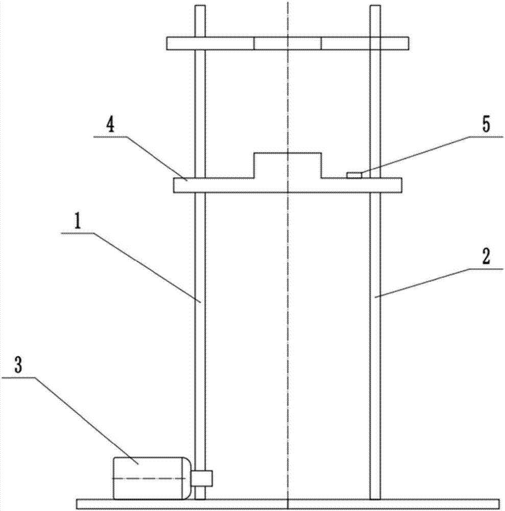
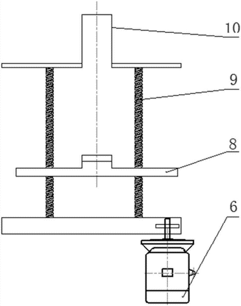
[0014] A synchronous lifting device for a MOX batch sintering furnace, including a synchronous lifting device, a synchronous circuit, and a furnace bottom lifting device. The furnace bottom lifting device includes a lifting motor 6, a furnace bottom cover 8, a lead screw 9, and a furnace body 10, wherein the lifting motor 6 The leading screw 9 is driven to rotate, and the leading screw 9 makes the furnace bottom cover 8 rise so as to approach the furnace body 10 . The synchronous lifting device includes a threaded screw 1, a guide rod 2, a synchronous motor 3, a simulated sintering furnace bottom 4, and a laser ranging sensor 5, wherein the synchronous motor 3 drives the threaded screw 1 to rotate, so that the threaded screw 1 and the guide rod The simulated sintering furnace bottom 4 on the 2 rises, and a laser ranging sensor 5 is installed on the simulated sintering furnace bottom 4.

[0015] Such as figure 2 As shown, in the synchronous circuit, the lifting motor 6 and th...


PUM


Abstract

An MOX batch sintering furnace synchronous lifting device comprises a synchronous lifting device, a synchronous circuit and a furnace bottom raising device. The furnace bottom raising device comprises a lifting motor 6, a furnace bottom cover 8, a lead screw 9 and a furnace body 10. The lifting motor 6 drives the lead screw 9 to rotate. The lead screw 9 enables the furnace bottom cover 8 to rise so as to be close to the furnace body 10. The synchronous lifting device comprises a threaded lead screw 1, a guide rod 2, a synchronous motor 3, a simulation sintering furnace bottom 4 and a laser ranging sensor 5. The synchronous motor 3 drives the threaded lead screw 1 to rotate, so that the simulation sintering furnace bottom 4 on the threaded lead screw 1 and the guide rod 2 are made to rise. Besides, the laser ranging sensor 5 is installed on the simulation sintering furnace bottom 4. In a synchronous circuit, the lifting motor 6 and the synchronous motor 3 are both connected with a signal detection and control circuit 7, the control circuit 7 can reduce the rotation speed of the lifting motor 6 and then transmits the rotation speed electrical signal to the synchronous motor 3, and therefore the lifting motor 6 and the synchronous motor 3 can synchronously conduct ascending and descending. The distance or lifting height of the furnace bottom cover 8 can be judged.

Description

technical field [0001] The invention belongs to the technical field of equipment state monitoring, and in particular relates to a synchronous lifting device for a MOX batch sintering furnace. Background technique [0002] The MOX fuel plant is the intermediate link between the reprocessing plant and the pressurized water reactor and fast reactor, and is the key link to realize the closed cycle of nuclear fuel in my country. Among them, MOX pellet sintering is one of the most critical processes for pellet preparation. Due to the high radioactivity of the sintered MOX pellets, the sintering furnace had to be sealed in a heavily shielded glove box. After the sintering furnace is enclosed by a shielded glove box, it greatly increases the difficulty for the staff to control it. The main disadvantages are as follows: the structure of the furnace is complicated. If a fault occurs during the lifting process, the workers cannot find the problem immediately, and they still operate t...

Claims


Application Information

Patent Timeline
Patent Type & Authority Applications(China)
IPC IPC(8): F27D1/18F27D19/00
CPCF27D1/1808F27D19/00F27D2001/1833F27D2019/0028
Inventor 周国梁潘传龙艾利君杨廷贵张顺孝孙江蒲小斌李军辉
Owner 中核四0四成都核技术工程设计研究院有限公司
Learn More