
Rocket recycling device with thermal infrared imager

A technology of infrared thermal imager and recovery device, which is applied to measurement devices, spacecraft landing devices, instruments, etc., can solve the problems of difficult control, damage, complicated equipment and recovery process, etc., achieves simple structure and principle, and solves explosion problems. Effect

Inactive Publication Date: 2017-12-26
FOSHAN SHENHANG SCI & TECH CO LTD
View PDF1 Cites 1 Cited by
  • Summary
  • Abstract
  • Description
  • Claims
  • Application Information

AI Technical Summary

Problems solved by technology

Some recovery methods at this stage are: one is parachute recovery. The empty arrow weighs 10 tons and keeps landing upright. When it falls to the ground, it will be damaged twice. If it falls sideways, most of it will be damaged. If it falls into the sea, it will be completely damaged. The salvage is for confidentiality.
The second is that the rocket developed by the United States recently landed vertically and succeeded in land-based experiments. However, the earth rotates, and most of its area is the sea, so it must land on the sea. The platform fluctuates due to waves, which affects the flight attitude. Therefore, every sea experiment Every time when it hit the ground, it tilted and exploded
[0004] The invention patent with publication number CN105783610A can solve this problem to a certain extent, but the equipment and recycling process of the invention are too complicated and difficult to control

Method used


Image

  • Rocket recycling device with thermal infrared imager
  • Rocket recycling device with thermal infrared imager
  • Rocket recycling device with thermal infrared imager

Examples


Embodiment Construction

[0013] The present invention will be further described below in conjunction with the accompanying drawings.

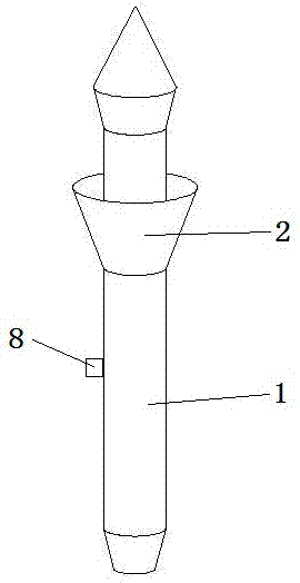
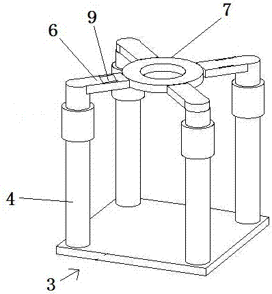
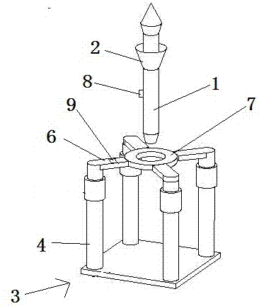
[0014] A rocket recovery device with an infrared thermal imaging camera, comprising a rocket recovery platform 3 and a rocket 1; a funnel device 2 is installed at the upper middle of the main body of the rocket 1, and the funnel device 2 is designed to surround the rocket 1 and is in the shape of a funnel, and The rocket 1 is fixed together; the rocket 1 is also equipped with an infrared thermal imager 2, which is used to identify and capture the position of the infrared light emitter 9; the rocket recovery platform 3 includes a support platform 7, an infrared light emitter 9, and four support frames 4 and a plurality of connecting rods 6; the connecting rod 6 is installed on the upper end of the support frame 4, and the other end of the connecting rod 6 is connected to the supporting platform 7, and the connecting rod 6 is designed around the supporting platform 7; the...


PUM


Abstract

A rocket recovery device with an infrared thermal imager, relating to the field of aerospace equipment recovery, including a rocket recovery platform and a rocket; the rocket recovery platform includes a support platform, an infrared light emitter, three or more support frames and multiple Connecting rod; the connecting rod is installed on the upper end of the supporting frame, and the other end of the connecting rod is connected to the supporting platform, and the connecting rod is designed to surround the supporting platform; a round hole is arranged in the middle of the supporting platform; a funnel device is installed in the upper part of the main body of the rocket; An infrared camera is also installed. The rocket flies back to the sky above the rocket recovery platform through high-precision GPS and other devices, opens the funnel device, and then lands at the middle of the support platform until the funnel device touches the support platform, and the gravity of the rocket fully acts on the support platform through the funnel device On, the rocket completes its landing. The structure and principle of the present invention are very simple, and can be applied to sea and land, and the present invention also well solves the problem that the rocket is easy to fall and cause explosion during the early recovery process.

Description

technical field [0001] A rocket recovery device with an infrared thermal imager relates to the field of space material recovery, in particular to a rocket recovery device. Background technique [0002] The launch vehicle is a space vehicle. The cost of the rocket engine is 60 million US dollars. The launch cost is 200,000 US dollars. At present, most of the launch vehicles are disposable space vehicles. After the first stage is separated, the rocket will fall to the uninhabited land or open sea , can not be reused, which increases the cost of aerospace research. [0003] If the first stage of the launch vehicle can be recovered at the moment of falling, the cost of aerospace research can be reduced. All countries are developing rocket recovery technology, but they all fail. Some recovery methods at this stage are: 1. Parachute recovery. The empty arrow weighs 10 tons and keeps landing upright. When it falls to the ground, it will be damaged twice. If it falls sideways, most...

Claims


Application Information

Patent Timeline
Patent Type & Authority Applications(China)
IPC IPC(8): F42B15/00F42B10/48B64G1/62G01J5/00
CPCF42B15/00B64G1/62F42B10/48G01J5/00G01J2005/0077
Inventor 黄华辉
Owner FOSHAN SHENHANG SCI & TECH CO LTD
Learn More